
Toyota Sienna Service Manual: Slide Door Closer LH does not Operate
DESCRIPTION
The slide door ECU LH controls the slide door closer. In response to the output signals from the switches in the slide door lock, the slide door closer drives the closer motor.
HINT: The slide door closer system operates regardless of the power slide door main switch ON / OFF.
WIRING DIAGRAM
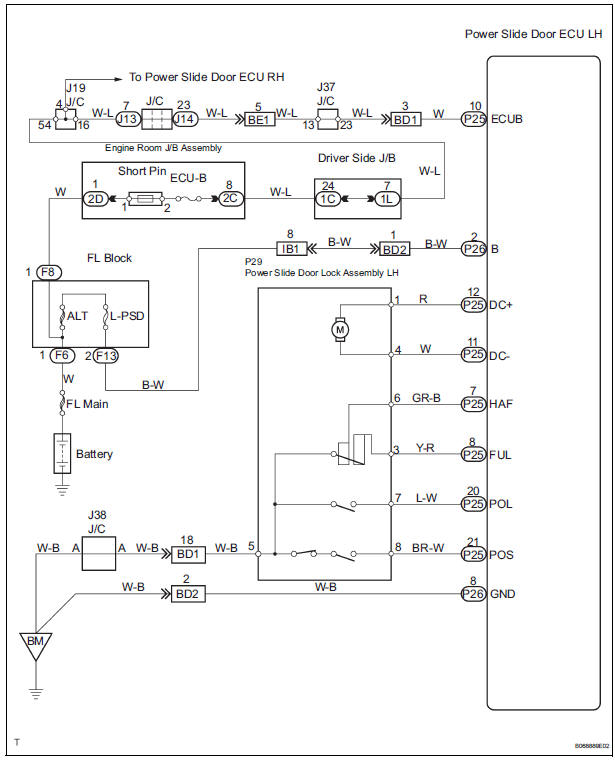
INSPECTION PROCEDURE
1 INSPECT FUSE (ECU-B)
- Inspect the ECU-B fuse
2 INSPECT SLIDE DOOR LOCK
- Check that the slide door fully closes (fully locked) when the door is closed by hand.
3 POWER SOURCE RESET
- Disconnect the ECU-B fuse and reconnect it. 10 seconds later, check that the slide door closer is operational.
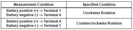
4 INSPECT POWER SLIDE DOOR LOCK ASSEMBLY
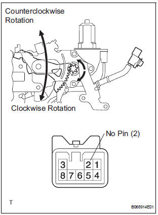
- Apply battery voltage to the terminals and check the motor operation.
OK
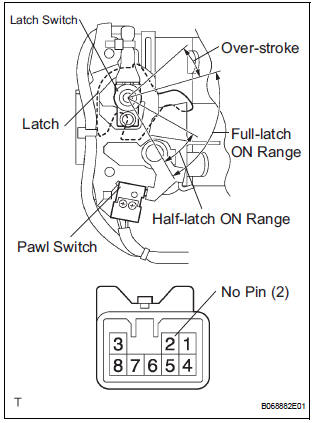
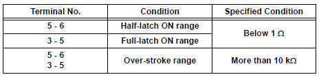
- At each range of the latch, inspect the resistance of the pawl switch and latch switch.
Resistance
- Inspect the resistance of the original position switch and handle switch.
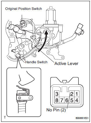
Resistance

5 CHECK WIRE HARNESS (POWER SLIDE DOOR LOCK ASSEMBLY - POWER SLIDE DOOR ECU LH)
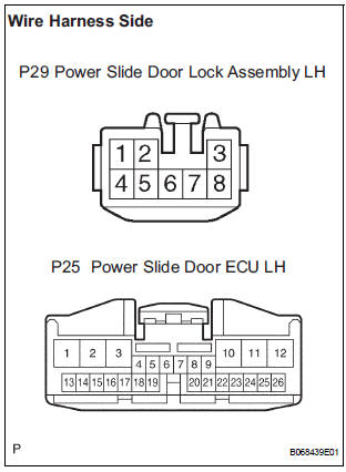
- Disconnect the P29 door lock and P25 ECU connectors.
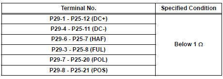
- Check the resistance between the wire harness connectors.
Resistance (Check for open circuit)
- Check the resistance between the P29 lock connector and body ground.
Resistance (Check for open circuit)

REPLACE POWER SLIDE DOOR ECU LH
 Data list / active test
1. DATA LIST
HINT:
Using the DATA LIST displayed on the intelligent tester,
you can read the value of the switch, sensor, actuator,
etc. without parts removal. Reading the DATA LIST as
the first ...
 Slide Door Closer RH does not Operate
DESCRIPTION
The slide door ECU RH controls the slide door closer. In response to the
signals output from the switches
in the slide door lock, the slide door closer drives the closer motor.
HINT:
...
Other materials:
Inspection
1. INSPECT RUNOUT OF DIFFERENTIAL RING GEAR
(a) Using a dial gauge , check the runout of the ring
gear.
Maximum runout:
0.07 mm (0.0028 in.)
If the runout is greater than the maximum, replace
the ring gear with a new one.
2. INSPECT DIFFERENTIAL RING GEAR BACKLASH
(a) Using a dial gauge, ...
EVAP System
RELATED DTCS
If any EVAP system DTCs are set, the malfunctioning area can be determined
using the table below.
NOTICE:
If the 0.02 inch reference pressure difference between the first and
second checks is greater than
the specification, the DTCs corresponding to the refe ...
Wireless remote control/
electronic key battery
Replace the battery with a new one if it is depleted.
You will need the following items:
Flathead screwdriver
Lithium battery CR2032
Replacing the battery
Vehicles without a smart key system
Remove the cover using a coin
protected with tape etc.
Remove the deplete ...
