Toyota Sienna Service Manual: Stop Light Switch Circuit Malfunction
DTC P0571 Stop Light Switch Circuit Malfunction
DESCRIPTION
The ECM receives the brake demand signal from the distance control ECU and transmits it to the skid control ECU (brake actuator assembly).
The skid control ECU (brake actuator assembly) receives a signal from the ECM and operates the brake actuator.
The skid control ECU (brake actuator assembly) operates the brake actuator and illuminates the stop light by operating the BRK relay at the same time.
|
DTC No. |
DTC Detection Condition |
Trouble Area |
|
P0571 |
This trouble code is output when the ECM detected the BRK relay error signal from the skid control ECU for 0.2 sec. or more while the dynamic cruise control is in operation. |
|
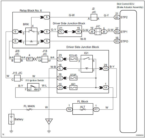
WIRING DIAGRAM
INSPECTION PROCEDURE
1 CHECK BRK RELAY
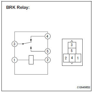
- Remove the BRK relay from the Relay Block No. 6.
- Measure the resistance according to the value(s) in the table below.
Standard resistance
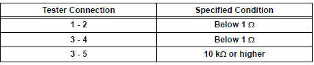
- Apply battery voltage between terminals 1 and 2.
- Measure the resistance according to the value(s) in the table below.
Standard resistance
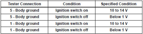
2 CHECK HARNESS AND CONNECTOR (BRK RELAY - BATTERY)
- Disconnect the connector from the Relay Block No. 6.
- Measure the voltage according to the value(s) in the table below.
Standard voltage
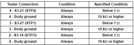
3 CHECK HARNESS AND CONNECTOR (BRK RELAY - SKID CONTROL ECU)
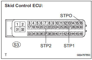
- Disconnect the S3 connector from the skid control ECU.
- Measure the resistance according to the value(s) in the table below.
Standard resistance
REPLACE BRAKE ACTUATOR ASSEMBLY
 Brake Switch "A" Circuit
DTC P0571 Brake Switch "A" Circuit
DESCRIPTION
When the brake pedal is depressed, the stop light switch sends a signal to
the ECM. When the ECM
receives this signal, it cancels the crui ...
 Control Module Performance
DTC P0607 Control Module Performance
DESCRIPTION
This DTC indicates a malfunction in the ECM.
HINT:
The ECM receives signals from each sensor to control all the functions of the
cruise control w ...
Other materials:
For automatic air conditioning system
ON-VEHICLE INSPECTION
1. INSPECT AIR INLET CONTROL SERVO MOTOR
(a) Remove the air inlet control servo motor.
(b) Connect the positive (+) lead from the battery to
terminal 4 and negative (-) lead to terminal 5, then
check that the lever turns to "RECIRCULATION"
side smoothly.
...
Removal
1. REMOVE BACK DOOR GARNISH CENTER
2. REMOVE BACK DOOR SIDE GARNISH LH
3. REMOVE BACK DOOR SIDE GARNISH RH
4. REMOVE BACK DOOR STRAP COVER
5. REMOVE BACK DOOR PULL STRAP
6. REMOVE BACK DOOR TRIM BOARD ASSEMBLY
7. REMOVE BACK DOOR SERVICE HOLE PLATE
8. REMOVE REAR SPOILER COVER (W/ REAR
SPOIL ...
High Temperature
DTC 58-45 High Temperature
DTC 80-45 High Temperature
DESCRIPTION
DTC No.
DTC Detection Condition
Trouble Area
58-45
High map disc player temperature is detected (Over
80C).
Radio and navigation assembly
80-45
High map disc player tem ...
