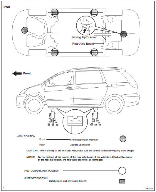
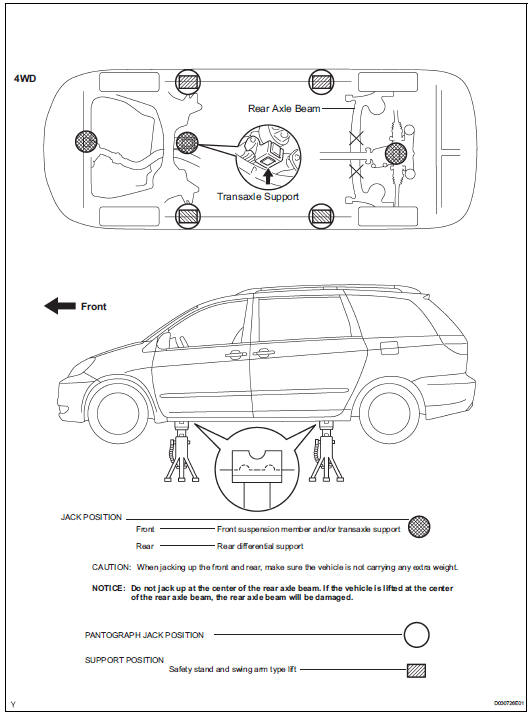
Toyota Sienna Service Manual: Vehicle lift and support locations
1. NOTICE ABOUT VEHICLE CONDITION WHEN JACKING UP VEHICLE
(a) The vehicle must be unloaded before jacking up/ lifting up the vehicle. Never jack up/lift up a heavily loaded vehicle.
(b) When removing heavy parts such as the engine and transmission, the center of gravity of the vehicle may shift. To stabilize the vehicle, place a balance weight in a location where it will not roll or shift, or use a transmission jack to hold the jacking support.
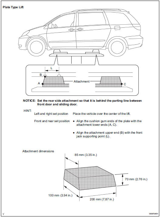
2. NOTICE FOR USING 4 POST LIFT
(a) Follow the safety procedures outlined in the lift instruction manual.
(b) Use precautionary measures to prevent the free wheel beam from damaging tires or wheels.
(c) Use wheel chocks to secure the vehicle.
3. NOTICE FOR USING JACK AND SAFETY STAND
(a) Work on a level surface. Use wheel chocks at all times.
(b) Set the jack and rigid racks to the specified locations of the vehicle accurately.
(c) When jacking up the vehicle, first release the parking brake and move the shift lever to N.
(d) When jacking up the entire vehicle: (1) When jacking up the front wheels first, make sure wheel chocks are behind the rear wheels.
(2) When jacking up the rear wheels first, make sure wheel chocks are in front of the front wheels.
(e) When jacking up only the front or rear wheels of the vehicle:
(1) Before jacking up the front wheels, place wheel chocks on both sides of the rear wheels.
(2) Before jacking up the rear wheels, place wheel chocks on both sides of the front wheels.
(f) When lowering a vehicle that only has its front or rear wheels jacked up:
(1) Before lowering the front wheels, make sure wheel chocks are in front of the rear wheels.
(2) Before lowering the rear wheels, make sure wheel chocks are behind the front wheels.
(g) It is extremely dangerous to perform any work on a vehicle raised on a jack alone, even for work that can be finished quickly. Rigid racks must be used to support the vehicle.
 Precaution for cooling fan system
NOTICE: • When the ignition switch is turned off and the
engine temperature is high, the cooling fans may
operate for approximately 3 minutes. • After turning the ignition switch
off, ke ...

Other materials:
Initialization
1. RESET MEMORY
NOTICE:
Perform the RESET MEMORY (AT initialization)
when replacing the automatic transaxle assembly,
engine assembly or ECM.
The RESET MEMORY can be performed only with
the Intelligent tester.
HINT:
The ECM memorizes the condition that the ...
Disc cannot be Played/ No Playable Files/ Copyright Protection Error
DTC 63-7D Disc cannot be Played
DTC 63-7E No Playable Files
DTC 63-7F Copyright Protection Error
DESCRIPTION
DTC No.
DTC Detection Condition
Trouble Area
63-7D
An incompatible MP3 / WMA file is used.
Although the file has an extension of &quo ...
Disassembly
1. REMOVE GENERATOR CLUTCH PULLEY
(A) using a screwdriver, remove the generator pulley
cap.
(b) Set SST (A) and (B).
SST 09820-63020
(c) Clamp SST (A) in a vise.
NOTICE:
Be sure to fix the flat surface of SST (A) in a
vise.
(d) Place the rotor shaft end int ...
