Toyota Sienna Service Manual: Terminals of ECU
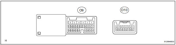
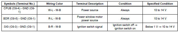
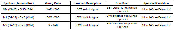
1. POSITION CONTROL ECU AND SWITCH ASSEMBLY (POWER SEAT CONTROL SWITCH AND ECU)
- Disconnect the P58 and P59 connectors.
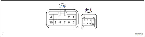
- Check the voltage of each terminal of the wire harness side connectors.
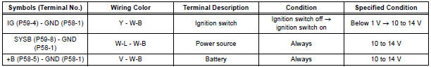
If the result is not as specified, there may be a malfunction in the wire harness side.
- Check the resistance of each terminal of the wire harness side connectors.

If the result is not as specified, there may be a malfunction in the wire harness side.
- Reconnect the P58 and P59 connectors.
- Check the voltage of each terminal of the connectors.
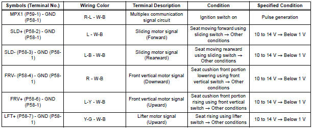
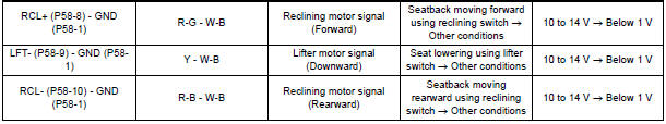
If the result is not as specified, the position control ECU and switch assembly may be malfunctioning.
2. OUTER MIRROR CONTROL ECU LH
- Disconnect the outer mirror control ECU LH connector.
- Check the voltage of each terminal of the wire harness side connectors.
If the result is not as specified, there may be a malfunction in the wire harness side.
- Check the resistance of each terminal of the wire harness side connector.

If the result is not as specified, there may be a malfunction in the wire harness side.
- Reconnect the outer mirror control ECU LH connector.
- Check the voltage of each terminal of the connectors.
If the result is not as specified, the outer mirror control ECU LH may be malfunctioning.
 Problem symptoms table
HINT:
Inspect the fuse and relay before confirming the suspected
areas in the table below.
Inspect each suspected area in numerical order for the
corresponding symptom.
If the ...
 Diagnosis system
1. DESCRIPTION
Front power seat control system data can be read
through the Data Link Connector 3 (DLC3) of the
vehicle. When the system seems to be
malfunctioning, use the intelligent ...
Other materials:
Automatic transaxle fluid
On-vehicle inspection
1. CHECK FLUID LEVEL
HINT:
Drive the vehicle so that the engine and transaxle are at
normal operating temperature.
Fluid temperature:
70 to 80°C (158 to 176°F)
(a) Park the vehicle on a level surface and set the
parking brake.
(b) With the engine idling and the ...
Inspection
1. INSPECT CHARCOAL CANISTER ASSEMBLY
(a) Visually check the charcoal canister for cracks or
damage.
If cracks or damage are found, replace the charcoal
canister assembly.
(b) Check charcoal canister operation.
(1) With the purge port closed, blow 1.67 kPa (17.0
gf/cm2, 0.24 psi) ...
Distance Control ECU Power Source Circuit
DESCRIPTION
This circuit provides power to operate the distance control ECU. The distance
control ECU determines
information about the vehicle in front based on data from the laser sensor, and
then decides how much
acceleration and/or deceleration is needed to maintain the set distance. The
...
