Toyota Sienna Service Manual: Diagnosis system
1. DESCRIPTION
- Front power seat control system data can be read through the Data Link Connector 3 (DLC3) of the vehicle. When the system seems to be malfunctioning, use the intelligent tester to check for malfunctions and perform repairs.
2. CHECK DLC3
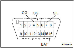
- The vehicle uses ISO 15765-4 communication protocol. The terminal arrangement of the DLC3 complies with SAE J1962 and matches the ISO 15765-4 format.
If the result is not as specified, the DLC3 may have a malfunction. Repair or replace the wire harness and connector.
HINT: Connect the cable of the intelligent tester to the DLC3, turn the ignition switch on and attempt to use the tester. If the screen displays a communication error message, a problem exists on the vehicle side or the tester side.
- If communication is normal when the tester is connected to another vehicle, inspect the DLC3 of the original vehicle.
- If communication is still not possible when the tester is connected to another vehicle, the problem is probably in the tester itself. Consult the Service Department listed in the tester's instruction manual.
3. INSPECT BATTERY VOLTAGE
- Check the battery voltage.
Voltage: 11 to 14 V
If the voltage is below 11 V, recharge or replace the battery before proceeding.
 Terminals of ECU
1. POSITION CONTROL ECU AND SWITCH ASSEMBLY
(POWER SEAT CONTROL SWITCH AND ECU)
Disconnect the P58 and P59 connectors.
Check the voltage of each terminal of the wire
harness sid ...
 Data list / active test
1. DATA LIST
HINT:
Using the intelligent tester's DATA LIST allows the status
of a switch, sensor, actuator and other items to be read
without removing any parts. Reading the DATA LIST
early in t ...
Other materials:
Power window master
switch
Inspection
1. INSPECT POWER WINDOW REGULATOR MASTER SWITCH ASSEMBLY (w/ Jam
Protection Function)
Check the resistance between the terminals of the
switch when the switch is operated.
Standard:
AUTO (driver side) switch
Passenger side switch
Rear LH switch
Rear RH switch
...
Removal
1. REMOVE NO. 1 ENGINE UNDER COVER (See page
EM-26)
2. REMOVE EXHAUST PIPE ASSEMBLY
for 2WD:(See page EX-2)
for 4WD:(See page EX-8)
3. DRAIN ENGINE COOLANT (See page CO-6)
4. DRAIN ENGINE OIL (See page LU-4)
5. REMOVE NO. 2 MANIFOLD STAY (See page EM-39)
6. REMOVE NO. 2 EXHAUST MANIFOLD HEAT ...
Removal
1. DISCONNECT CABLE FROM NEGATIVE BATTERY
TERMINAL
2. REMOVE HEATED OXYGEN SENSOR (for Bank 1
Sensor 2)
(a) Disconnect the sensor connector under the center
console.
(b) Using SST, remove the heated oxygen sensor.
SST 09224-00010
3. REMOVE FRONT EXHAUST PIPE ASSEMBLY
(a) Disconnect ...
