Toyota Sienna Service Manual: Terminals of ECU
1. CHECK POWER SLIDE DOOR ECU LH
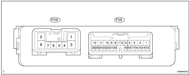
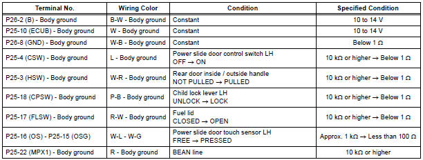
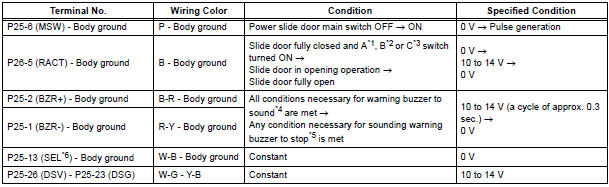
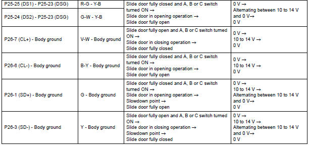
- Disconnect the P25 and P26 ECU connectors, and check the voltage and resistance of each terminal of the wire harness side connectors
If the result is not as specified, there may be a malfunction on the wire harness side.
- Reconnect the ECU connectors, and check the voltage of each terminal of the connectors.
*1 Satellite switch (Slide door LH)
*2 Power slide door control switch LH
*3 Transmitter switch (Slide door LH)
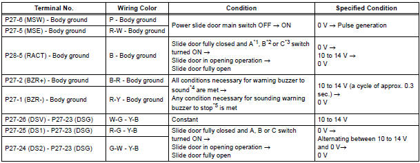
*4 When all the conditions listed below are met, the
warning buzzer sounds.
- Ignition switch is turned ON
- Shift lever is moved into any position except P position
- Slide door is open or power slide door system is activated to open
*5 When any condition listed below is met, the sounding warning buzzer stops.
- Shift lever is moved into P position
- Slide door is fully closed
*6 Terminal SEL is used for distinction between the power slide door ECU LH and RH. Only terminal SEL of the power slide door ECU LH is grounded.
HINT: Use an oscilloscope to check the output voltages of the power slide door main switch, buzzer and pulse sensor.
If the result is not as specified, the ECU may have a malfunction.
2. CHECK POWER SLIDE DOOR ECU RH
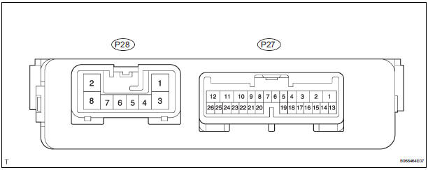
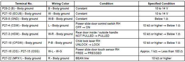
- Disconnect the P27 and P28 ECU connectors, and check the voltage or resistance of each terminal of the wire harness side connectors.
If the result is not as specified, there may be a malfunction on the wire harness side.
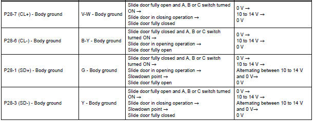
- Reconnect the ECU connectors, and check the voltage of each terminal of the connectors.
*1 Satellite switch (Slide door RH)
*2 Power slide door control switch RH
*3 Transmitter switch (Slide door RH)
*4 When all the conditions listed below are met, the
warning buzzer sounds.
- Ignition switch is turned ON
- Shift lever is moved into any position except P position
- Slide door is open or power slide door system is activated to open
*5 When any condition listed below is met, the sounding warning buzzer stops.
- Shift lever is moved into P position
- Slide door is fully closed
HINT: Use an oscilloscope to check the output voltages of the power slide door main switch, buzzer and pulse sensor.
If the result is not as specified, the ECU may have a malfunction.
 Problem symptoms table
POWER SLIDE DOOR SYSTEM
Symptom
Suspected Area
Power slide door LH does not operate when switch* is
pressed (* switch indicates satellite switch for power
slide door ...
 Diagnosis system
1. CHECK DLC3
The vehicle's ECU uses ISO 15765-4 for
communication protocol. The terminal arrangement
of the DLC3 complies with SAE J1962 and matches
the ISO 15765-4 format
NOTICE:
...
Other materials:
How to proceed with
troubleshooting
1 VEHICLE BROUGHT TO WORKSHOP
2 CUSTOMER PROBLEM ANALYSIS
3 CHECK INITIAL CHECK FUNCTION
4 PROBLEM SYMPTOMS TABLE
THE CORRESPONDING SYSTEM DOES NOT EXIST (Go to step 5)
5 BASED ON THE MALFUNCTION SYMPTOM, PERFORM THE TROUBLESHOOTING
BELOW
Operation check (C).
Terminals of ECU
6 ...
Air fuel ratio sensor relay
INSPECTION
1. INSPECT AIR FUEL RATIO SENSOR RELAY
Using an ohmmeter, measure the resistance
according to the value(s) in the table below.
Standard resistance
If the result is not as specified, replace the relay. ...
Services
Subscribers have the following Safety Connect services available:
Automatic Collision Notification*
Helps drivers receive necessary response from emergency service providers.
*: U.S. Patent No. 7,508,298 B2
Stolen Vehicle Location
Helps drivers in the event of vehicle theft.
Emergenc ...
