Toyota Sienna Service Manual: Transmitter ID not Registered
DTC C2171/71 Transmitter ID not Registered
DESCRIPTION
The IDs of each tire pressure warning valve and transmitters are registered to the tire pressure warning ECU.
When the IDs have never been registered, a DTC is output.

INSPECTION PROCEDURE
NOTICE:
- When replacing the tire pressure warning ECU, read the IDs stored in the ECU using the intelligent tester and note them down before removal.
- It is necessary to perform initialization (See page TW-23) after registration (See page TW-20) of the transmitter IDs into the tire pressure warning ECU after the ECU has been replaced.
1 CONFIRM REGISTRATION CONDITION (REGISTERED ID CODES)
(a) Make sure that the ignition switch is off.
(b) Connect the intelligent tester to the DLC3.
(c) Turn the ignition switch to the ON position.
(d) Select REGIT ID CODE by following the prompts displayed on the intelligent tester.
TIRE PRESSURE: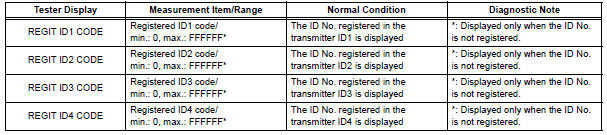
OK: The registered transmitter ID codes are displayed on the intelligent tester screen.

REPLACE TIRE PRESSURE WARNING ECU (See page TW-87)
2 PERFORM REGISTRATION (TRANSMITTER ID)
(a) Register the transmitter IDs for all the wheels (See page TW-20).

3 PERFORM INITIALIZATION
(a) Perform initialization (See page TW-23).

4 READ VALUE ON DATA LIST
(a) Make sure that the ignition switch is off.
(b) Connect the intelligent tester to the DLC3.
(c) Turn the ignition switch to the ON position.
(d) Select "TIREPRESS" by following the prompts displayed on the intelligent tester.
TIRE PRESSURE:
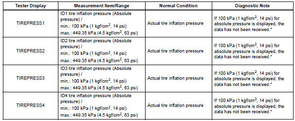
HINT: *: It may take about 5 to 6 minutes until the values are displayed. If the values are not displayed after a few minutes, perform troubleshooting according to the inspection procedure for DTCs C2121/21 to C2124/24 (See page TW-42).
Result 

END
 Abnormal Temperature Inside ID1 Tire
DESCRIPTION
Each tire pressure warning valve and transmitter measures the internal
temperature of its tire as well as
tire pressure, and transmits the information to the tire pressure warning ...
 Receiver Error
DTC C2176/76 Receiver Error
DESCRIPTION
The signals are transmitted to the tire pressure warning antenna and receiver
on the body as radio waves
and then sent to the tire pressure warning ECU.
...
Other materials:
Repair
1. REPAIR REAR WINDOW DEFOGGER WIRE
Clean the broken wire tips with grease, wax and
silicone remover.
Place the masking tape along the both sides of the
wire.
Thoroughly mix the repair agent (Dupont paste No.
4817).
Using a fine tip brush, apply a smal ...
Half Connection in Center Airbag Sensor
Assembly Connectors
DTC B1135/24 Half Connection in Center Airbag Sensor
Assembly Connectors
DESCRIPTION
The center airbag sensor assembly connector has a mechanism that electrically
detects half connection.
The center airbag sensor assembly monitors the voltage applied to the
disconnection detection pins and ...
MIL Circuit
DESCRIPTION
The MIL (Malfunction Indicator Lamp) is used to indicate vehicle malfunctions
detected by the ECM.
When the ignition switch is turned to the ON position, power is supplied to the
MIL circuit, and the ECM
provides the circuit ground which illuminates the MIL.
The MIL operation ...
