Toyota Sienna Service Manual: Receiver Error
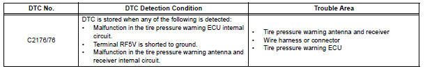
DTC C2176/76 Receiver Error
DESCRIPTION
The signals are transmitted to the tire pressure warning antenna and receiver on the body as radio waves and then sent to the tire pressure warning ECU.
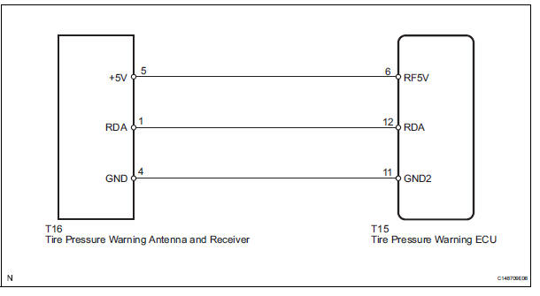
WIRING DIAGRAM
INSPECTION PROCEDURE
NOTICE:
- When replacing the tire pressure warning ECU, read the IDs stored in the ECU using the intelligent tester and write them down before removal.
- It is necessary to perform initialization (See page TW-23) after registration (See page TW-20) of the transmitter IDs into the tire pressure warning ECU after the ECU has been replaced.
1 CHECK HARNESS AND CONNECTOR (ECU - RECEIVER)
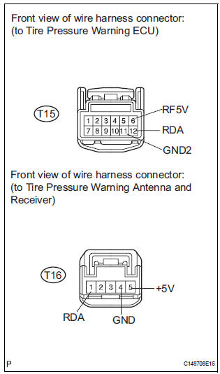
(a) Disconnect the T15 ECU connector.
(b) Disconnect the T16 receiver connector.
(c) Measure the resistance according to the value(s) in the table below.
Standard resistance 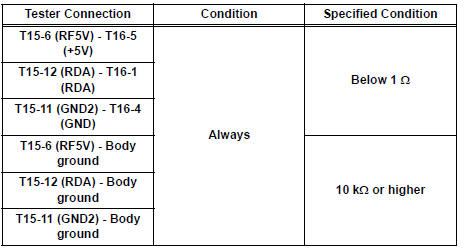

2 CHECK TIRE PRESSURE WARNING ECU
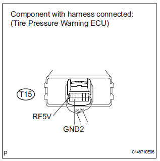
(a) Reconnect the T15 ECU connector.
(b) Turn the ignition switch to the ON position.
(c) Measure the voltage according to the value(s) in the table below.
Standard voltage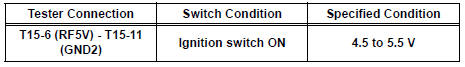

REPLACE TIRE PRESSURE WARNING ANTENNA AND RECEIVER (See page TW-81)
 Transmitter ID not Registered
DTC C2171/71 Transmitter ID not Registered
DESCRIPTION
The IDs of each tire pressure warning valve and transmitters are registered
to the tire pressure warning
ECU.
When the IDs have never bee ...
 Initialization not Completed
DTC C2177/77 Initialization not Completed
DESCRIPTION
Initialization is necessary after replacing any of the ECUs, tires with
different tire pressure, or tire pressure
warning valve and transmitt ...
Other materials:
DVD-ROM Abnormal
DTC 44-43 DVD-ROM Abnormal
DESCRIPTION
DTC No.
DTC Detecting Condition
Trouble Area
44-43
DVD-ROM operation is abnormal.
DVD
Television display assembly
INSPECTION PROCEDURE
HINT:
After the inspection is completed, clear the ...
Diagnosis system
1. DESCRIPTION
When troubleshooting OBD II (On-Board
Diagnostics) vehicles, an intelligent tester
(complying with SAE J1987) must be connected to
the DLC3 (Data Link Connector 3) of the vehicle.
Various data in the vehicle's ECM (Engine Control
Module) can be then read.
& ...
Vehicle lift and support locations
1. NOTICE ABOUT VEHICLE CONDITION WHEN
JACKING UP VEHICLE
(a) The vehicle must be unloaded before jacking up/
lifting up the vehicle. Never jack up/lift up a heavily
loaded vehicle.
(b) When removing heavy parts such as the engine and
transmission, the center of gravity of the vehicle
may s ...
