Toyota Sienna 2010-2026 Owners Manual: Windshield wipers and washer
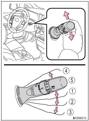
Operating the wiper lever
The wiper operation is selected by moving the lever as follows.
The illustration is intended as an example.
- Intermittent windshield wipers with interval adjuster
 *1 or
*1 or
 *2
*2
Intermittent windshield wiper operation *1 or
*1 or
 *2
*2
Low speed windshield wiper operation *1 or
*1 or
 *2
*2
High speed windshield wiper operation *1 or
*1 or
 *2
*2
Temporary operation *1 or
*1 or
 *2
*2
Off
*1: For U.S.A.
*2: For Canada
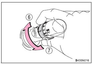
Wiper intervals can be adjusted when intermittent operation is selected.
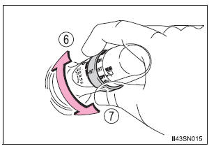
- Increases the intermittent windshield wiper frequency
- Decreases the intermittent windshield wiper frequency
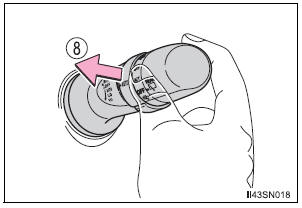
- Washer/wiper dual operation
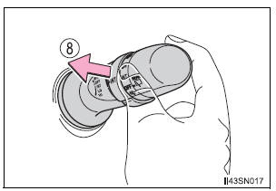
The wipers will automatically operate a couple of times after the washer squirts.
- Rain-sensing windshield wipers (if equipped)
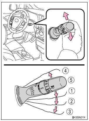
- Rain-sensing wiper
operation (ÔÇťAUTOÔÇŁ)
When ÔÇťAUTOÔÇŁ is selected,
the wipers will operate
automatically when the
sensor detects falling rain.
The system automatically adjusts wiper timing in accordance with rain volume.
 *1 or
*1 or
 *2
*2
Low speed wiper operation *1 or
*1 or
 *2
*2
High speed wiper operation *1 or
*1 or
 *2
*2
Temporary operation *1 or
*1 or
 *2
*2
Off
*1: For U.S.A.
*2: For Canada
The sensor sensitivity can be adjusted when ÔÇťAUTOÔÇŁ is selected.
- Increases the sensitivity
- Decreases the sensitivity
- Washer/wiper dual operation
The wipers will automatically operate a couple of times after the washer squirts.
The windshield wipers and washer can be operated when
The engine switch is in the ÔÇťONÔÇŁ position (vehicles without a smart key system) or IGNITION ON mode (vehicles with a smart key system).
Raindrop sensor (vehicles with rain-sensing windshield wipers)
- The raindrop sensor judges the amount of raindrops.
- If the wiper switch is turned to ÔÇťAUTOÔÇŁ position while the engine switch is in IGNITION ON mode, the wiper will operate once to show that ÔÇťAUTOÔÇŁ mode is activated.
- If the temperature of the raindrop sensor is 185┬░F (85┬░C) or higher, or 14┬░F (-10┬░C) or lower, automatic operation may not occur. In this case, operate the wipers in any mode other than ÔÇťAUTOÔÇŁ.
If no windshield washer fluid sprays
Check that the washer nozzles are not blocked if there is washer fluid in the windshield washer fluid reservoir.
| WARNING Caution regarding the use of windshield wipers in ÔÇťAUTOÔÇŁ mode The windshield wipers may operate unexpectedly if the sensor is touched or the windshield is subject to vibration in ÔÇťAUTOÔÇŁ mode. Take care that your fingers etc. do not become caught in the windshield wipers. Caution regarding the use of washer fluid When it is cold, do not use the washer fluid until the windshield becomes warm. The fluid may freeze on the windshield and cause low visibility. This may lead to an accident, resulting in death or serious injury. |
| NOTICE When the windshield is dry Do not use the wipers, as they may damage the windshield. When the washer fluid tank is empty Do not operate the switch continually as the washer fluid pump may overheat. When a nozzle becomes blocked In this case, contact your Toyota dealer. Do not try to clear it with a pin or other object. The nozzle will be damaged. |
 Fog light switch
The fog lights secure excellent visibility in difficult driving
conditions,
such as in rain and fog.
The illustration is intended as an example.
Turns the fog lights on
*1 or
*2
Tur ...
 Rear window wiper and
washer
Rear window wiper and
washer
Operating the wiper lever
Turning the end of the lever turns on the rear window wiper and
washer.
The illustration is intended as an example.
*1 or
*2
Intermittent window
wiper oper ...
Other materials:
Abnormal Temperature Inside ID1 Tire
DESCRIPTION
Each tire pressure warning valve and transmitter measures the internal
temperature of its tire as well as
tire pressure, and transmits the information to the tire pressure warning ECU
along with the transmitter ID.
If the measured temperature is out of the specified range, t ...
Turning on the high beam headlights
With the headlights on, push
the lever away from you to turn
on the high beams.
When the light switch is in
position, the Automatic High Beam
system will be activated.
Pull the lever toward you to the
center position to turn the high
beams off.
Pull the lever toward you and ...
Phone Display Settings
Display the ÔÇťPhone/Message SettingsÔÇŁ screen.
Select ÔÇťPhone Display SettingsÔÇŁ.
Select the desired item to be set.
Change the incoming call
display.
ÔÇťFull ScreenÔÇŁ: When a call is
received, the hands-free screen
is displayed and can be operated
on the screen.
...
