Toyota Sienna Service Manual: Disassembly
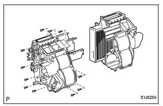
1. REMOVE BLOWER ASSEMBLY
(a) Remove the 2 screws and the blower assembly.
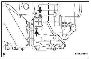
2. REMOVE MODE DAMPER SERVO SUB-ASSEMBLY
(a) Remove the 3 screws and the mode damper servo sub-assembly.
3. REMOVE AIRMIX DAMPER SERVO SUB-ASSEMBLY
(a) Remove the 3 screws and the airmix damper servo sub-assembly.
4. REMOVE NO. 2 AIRMIX DAMPER SERVO SUBASSEMBLY (for Automatic Air Conditioning System)
(a) Remove the 3 screws and the No. 2 airmix damper servo sub-assembly.
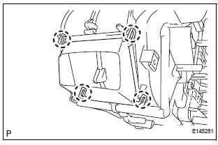
5. REMOVE NO. 1 HEATER CLAMP
(a) Release the 4 claw fittings and remove the No. 1 heater clamp.
6. REMOVE NO. 3 AIR CONDITIONING RADIATOR BRACKET
(a) Remove the screw and the No. 3 air conditioning radiator bracket.
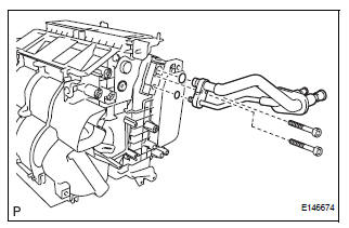
7. REMOVE HEATER RADIATOR UNIT SUB-ASSEMBLY
(a) Remove the heater radiator unit sub-assembly from the air conditioning radiator assembly.
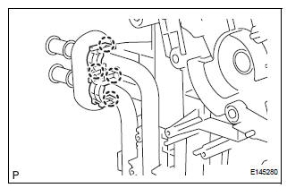
8. REMOVE AIR CONDITIONING TUBE ASSEMBLY
(a) Using a hexagon wrench 4.0 mm (0.15 in.), remove the 2 hexagon bolts and the air conditioning tube assembly.
(b) Remove the 2 O-rings from the air conditioning tube assembly.
9. REMOVE COOLER EXPANSION VALVE
(a) Remove the cooler expansion valve from the No. 1 cooler evaporator sub-assembly.
(b) Remove the 2 O-rings from the No. 1 cooler evaporator sub-assembly.
10. REMOVE NO. 2 AIR CONDITIONING RADIATOR BRACKET
(a) Remove the 2 screws and the No. 2 air conditioning radiator bracket.
11. REMOVE NO. 1 AIR CONDITIONING RADIATOR BRACKET
(a) Remove the 3 screws and the No .1 air conditioning radiator bracket.
12. REMOVE NO. 4 AIR CONDITIONING RADIATOR BRACKET
(a) Remove the No. 4 air conditioning radiator bracket.
13. REMOVE NO. 1 AIR DUCT
(a) Release the 4 claw fittings and remove the No. 1 air duct.
14. REMOVE NO. 1 COOLER THERMISTOR
(a) Disengage the clamp.
(b) Remove the 2 screws.
(c) Remove the 11 screws.
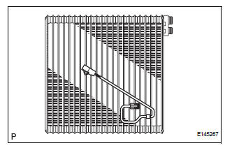
(d) Remove the No. 1 cooler thermistor.
 Removal
1. RECOVER REFRIGERANT FROM REFRIGERATION
SYSTEM (See page AC-172)
2. REMOVE FRONT WIPER ARM HEAD CAP (See page
WW-4)
3. REMOVE FRONT WIPER ARM RH (See page WW-4)
4. REMOVE FRONT WIPER ARM LH (Se ...
 Reassembly
1. INSTALL NO. 1 COOLER THERMISTOR
(a) Install the No. 1 cooler thermistor as shown in the
illustration.
NOTICE:
Be sure to insert the thermistor only once
because reinserting it will no ...
Other materials:
Disassembly
1. REMOVE FUEL TANK TO FILLER PIPE HOSE (See
page FU-43)
2. REMOVE FUEL TANK MAIN TUBE SUB-ASSEMBLY
(a) Remove the tube joint clip, and pull out the fuel main
tube.
NOTICE:
Check if there is any dirt or mud around the
connector before this operation and remove
the dirt as ...
The Other Caller's Voice cannot be Heard, is too Quiet, or Distorted
INSPECTION PROCEDURE
1 CHECK CELLULAR PHONE
Check if the voice on the other side can be heard using a
cellular phone.
OK:
Voice can be heard
2 CHECK NAVIGATION SYSTEM
Check that navigation sound can be heard from the
driver side speaker.
OK:
Audio sound can be heard
3 CHECK SE ...
Installation
1. INSTALL NO. 1 REAR DIFFERENTIAL SUPPORT
(a) Install the No. 1 rear differential support to the rear
differential carrier assembly with the 2 bolts and 2
nuts.
Torque: 85 N*m (867 kgf*cm, 63 ft.*lbf)
HINT:
Hold the bolt and tighten the nut.
2. INSTALL REAR DIFFERENTIAL DYNAMIC DAMPER
...
