Toyota Sienna Service Manual: A/C ECU Communication Stop
DTC B1262 A/C ECU Communication Stop
DESCRIPTION
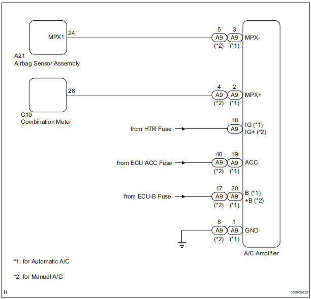
DTC B1262 is output when communication between the A/C amplifier and the multiplex network gateway ECU stops for more than 10 seconds.
|
DTC No. |
DTC Detection Condition |
Trouble Area |
|
B1262 |
A/C ECU communication stops |
|
WIRING DIAGRAM
INSPECTION PROCEDURE
1 CHECK HARNESS AND CONNECTOR (A/C AMPLIFIER - BATTERY)
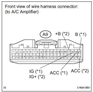
- Disconnect the A9 connector.
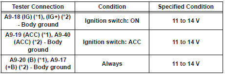
- Measure the voltage according to the value(s) in the table below.
Standard voltage
HINT:
*1: for Automatic A/C
*2: for Manual A/C
2 CHECK HARNESS AND CONNECTOR (A/C AMPLIFIER - GROUND)
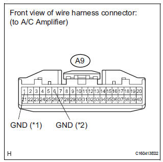
- Measure the resistance according to the value(s) in the table below.
Standard resistance
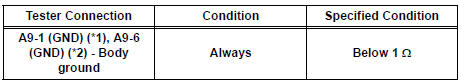
HINT:
*1: for Automatic A/C
*2: for Manual A/C
3 CHECK COMMUNICATION LINE
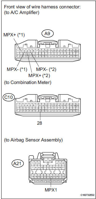
- Disconnect the C10 and A21 connectors.
- Measure the resistance according to the value(s) in the table below.
Standard resistance
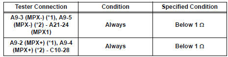
HINT:
*1: for Automatic A/C
*2: for Manual A/C
Result
REPLACE A/C AMPLIFIER
 Rear Door ECU LH Communication Stop
DTC B1217 Rear Door ECU LH Communication Stop
DESCRIPTION
DTC B1217 is output when communication between the power slide door ECU LH
and the multiplex
network gateway ECU stops for more than 10 s ...
 Combination Meter ECU Communication Stop
DTC B1271 Combination Meter ECU Communication Stop
DESCRIPTION
DTC B1271 is output when communication between the combination meter and the
multiplex network
gateway ECU stops for more than 10 se ...
Other materials:
Short to GND in Front Pretensioner Squib LH
Circuit
DTC B0137/71 Short to GND in Front Pretensioner Squib LH
Circuit
DESCRIPTION
The front pretensioner squib LH circuit consists of the center airbag sensor
assembly and the front seat
outer belt assembly LH.
This circuit instructs the SRS to deploy when deployment conditions are met.
DTC B ...
Front Occupant Classification Sensor LH Circuit
Malfunction
DTC B1780 Front Occupant Classification Sensor LH Circuit
Malfunction
DESCRIPTION
The front occupant classification sensor LH circuit consists of the occupant
classification ECU and the
front occupant classification sensor LH.
DTC B1780 is recorded when a malfunction is detected in the fron ...
Reassembly
1. INSTALL REAR DOOR WIRE SUB-ASSEMBLY LH
Install the wire.
NOTICE:
When installing the wire, push the areas where
the clips are installed in order to prevent
damage and deformation.
Install the 2 screws
2. INSTALL REAR DOOR LOCK ASSEMBLY LH
Apply MP grease to the slidin ...
