Toyota Sienna Service Manual: Rear Door ECU LH Communication Stop
DTC B1217 Rear Door ECU LH Communication Stop
DESCRIPTION
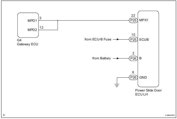
DTC B1217 is output when communication between the power slide door ECU LH and the multiplex network gateway ECU stops for more than 10 seconds.
|
DTC No. |
DTC Detection Condition |
Trouble Area |
|
B1217 |
RL-DOOR ECU communication stops |
|
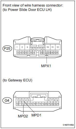
WIRING DIAGRAM
INSPECTION PROCEDURE
1 CHECK HARNESS AND CONNECTOR (POWER SLIDE DOOR ECU LH - BATTERY)
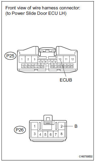
- Disconnect the P25 and P26 ECU connectors.
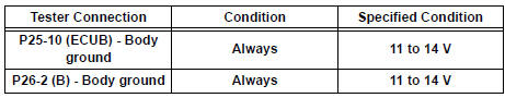
- Measure the voltage according to the value(s) in the table below.
Standard voltage
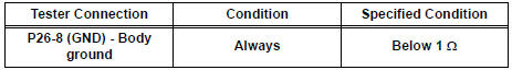
2 CHECK HARNESS AND CONNECTOR (POWER SLIDE DOOR ECU LH - GROUND)
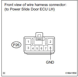
- Measure the resistance according to the value(s) in the table below.
Standard resistance
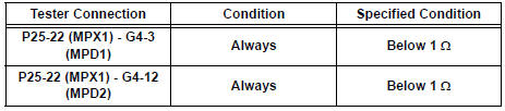
3 CHECK COMMUNICATION LINE
- Disconnect the G4 ECU connector.
- Measure the resistance according to the value(s) in the table below.
Standard resistance
Result
REPLACE POWER SLIDE DOOR ECU LH
 Rear Door ECU RH Communication Stop
DTC B1216 Rear Door ECU RH Communication Stop
DESCRIPTION
DTC B1216 is output when communication between the power slide door ECU RH
and the multiplex
network gateway ECU stops for more than 10 s ...
 A/C ECU Communication Stop
DTC B1262 A/C ECU Communication Stop
DESCRIPTION
DTC B1262 is output when communication between the A/C amplifier and the
multiplex network gateway
ECU stops for more than 10 seconds.
...
Other materials:
Registration
1. REGISTRATION TRANSMITTER CODE
HINT:
The garage door opener is built in the dome lamp
assembly No.1. When transmitter codes for garage door,
gate, entry gate, door lock, home lighting system or
security system are registered with the garage door
opener, be sure to register them again wheneve ...
Power Slide Door Pulse Sensor Malfunction on
Rear Left Door
DTC B2224 Power Slide Door Pulse Sensor Malfunction on
Rear Left Door
DESCRIPTION
A pulse sensor is built into slide door LH for jam and foreign
object detection and for slide door position
detection. The jam and foreign object detection feature of the pulse sensor
monitors the o ...
Engine compartment
Items
Check points
Battery
Check connections
Brake fluid
Is the brake fluid at the correct level?
Engine coolant
Is the engine coolant at the correct
level?
Engine oil
Is the engine oil at the correct level?
Exhaust system ...
