Toyota Sienna Service Manual: Combination Meter ECU Communication Stop
DTC B1271 Combination Meter ECU Communication Stop
DESCRIPTION
DTC B1271 is output when communication between the combination meter and the multiplex network gateway ECU stops for more than 10 seconds.
|
DTC No. |
DTC Detection Condition |
Trouble Area |
|
B1271 |
Combination meter communication stops |
|
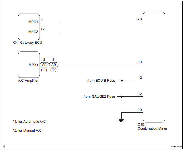
WIRING DIAGRAM
INSPECTION PROCEDURE
1 CHECK HARNESS AND CONNECTOR (COMBINATION METER - BATTERY)
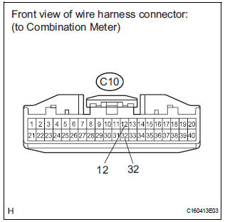
- Disconnect the C10 connector.
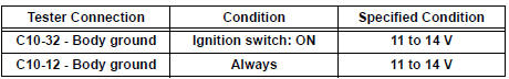
- Measure the voltage according to the value(s) in the table below.
Standard voltage
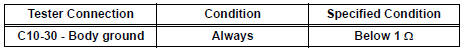
2 CHECK HARNESS AND CONNECTOR (COMBINATION METER - GROUND)
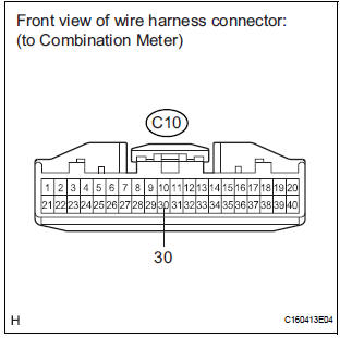
- Measure the resistance according to the value(s) in the table below.
Standard resistance
3 CHECK COMMUNICATION LINE
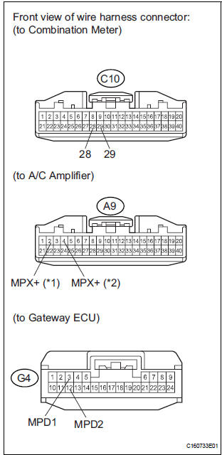
- Disconnect the A9 and G4 connectors.
- Measure the resistance according to the value(s) in the table below.
Standard resistance

HINT:
*1: for Automatic A/C
*2: for Manual A/C
Result
REPLACE COMBINATION METER
 A/C ECU Communication Stop
DTC B1262 A/C ECU Communication Stop
DESCRIPTION
DTC B1262 is output when communication between the A/C amplifier and the
multiplex network gateway
ECU stops for more than 10 seconds.
...
 Power Seat ECU Communication Stop
DTC B1272 Power Seat ECU Communication Stop
DESCRIPTION
This DTC is detected when communication between the seat position control ECU
and the multiplex
network gateway ECU stops for more than 10 ...
Other materials:
System description
1. GENERAL DESCRIPTION
The power seat control system is equipped with the
following function:
The front seats are equipped with electric
adjuster slide, reclining, lifter, front vertical and
lumbar support adjustment functions.
The power seat control system (w ...
Manual Up / Down Function does not Operate on Rear RH Only
DESCRIPTION
If the manual UP/DOWN function does not operate, the power window motor, the
regulator switch or the
wire harness may be malfunctioning.
WIRING DIAGRAM
INSPECTION PROCEDURE
1 CHECK WIRE HARNESS (POWER SOURCE)
Disconnect the P39 regulator switch connector.
Turn ...
Short to B+ in Rear Curtain Shield Squib LH
Circuit
DTC B1638/86 Short to B+ in Rear Curtain Shield Squib LH
Circuit
DESCRIPTION
The rear curtain shield squib LH circuit consists of the center airbag sensor
assembly and the curtain
shield airbag assembly LH.
The circuit instructs the SRS to deploy when deployment conditions are met.
DTC B ...
