Toyota Sienna Service Manual: Adjustment
HINT:
- On the RH side, use the same procedures as on the LH side.
- Since a centering bolt is used as door hinge mounting bolts on the body side and the door side, the door cannot be adjusted with them on. Substitute a bolt with a washer for the centering bolt.
1. INSPECT BACK DOOR PANEL SUB-ASSEMBLY
- Check that the clearance is within the standard range
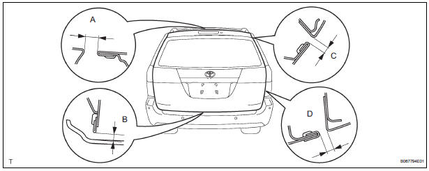
Standard

2. ADJUST BACK DOOR PANEL SUB-ASSEMBLY
- Adjust the door forward / rearward and vertically by loosening the body side hinge nuts and bolt.
- Tighten the body side hinge nuts and bolt after the
adjustment.
Torque: 19.5 N*m (200 kgf*cm, 14 ft.*lbf)
- Horizontally and vertically adjust the door by loosening the door side hinge bolts.
- Tighten the body side hinge bolts after the
adjustment.
Torque: 19.5 N*m (200 kgf*cm, 14 ft.*lbf)
- Using a screwdriver, remove the back door scuff plate.
HINT: Tape the screwdriver tip before use.
- Adjust the striker position by slightly loosening the striker mounting screws and hitting the striker with a plastic-faced hammer.
- Tighten the striker mounting screws after the
adjustment.
Torque: 27 N*m (275 kgf*cm, 20 ft.*lbf)
 Disassembly
HINT:
When the battery is reconnected, the back door is locked and
cannot be opened. Therefore, it is necessary to unlock the
back door using the door control switch or transmitter switch.
1. REMO ...
 Reassembly
1. INSTALL BACK DOOR STOPPER LOWER
Install the 2 stoppers with the 4 bolts.
Torque: 7.0 N*m (71 kgf*cm, 62 in.*lbf)
2. INSTALL BACK DOOR BASE STOPPER BRACKET
Install the 2 brackets with t ...
Other materials:
Air conditioning pressure sensor
ON-VEHICLE INSPECTION
1. INSPECT A/C PRESSURE SENSOR
(a) Install the manifold gauge set.
(b) Disconnect the connector from the A/C pressure
sensor.
(c) Connect the three 1.5 V dry cell batteries' positive
(+) lead to terminal 3 and the negative (-) lead to
terminal 1.
(d) Connect t ...
MIL Circuit
DESCRIPTION
The MIL (Malfunction Indicator Lamp) is used to indicate vehicle malfunctions
detected by the ECM.
When the ignition switch is turned to the ON position, power is supplied to the
MIL circuit, and the ECM
provides the circuit ground which illuminates the MIL.
The MIL operation ...
How to proceed with
troubleshooting
HINT:
*: Use the intelligent tester.
1 VEHICLE BROUGHT TO WORKSHOP
2 CUSTOMER PROBLEM ANALYSIS
(a) Confirm problem symptoms
3 CHECK MULTIPLEX COMMUNICATION SYSTEM*
Check if the multiplex communication system DTC is output.
HINT:
The center airbag sensor assembly of this system ...
