Toyota Sienna Service Manual: Reassembly
1. INSTALL BACK DOOR STOPPER LOWER
- Install the 2 stoppers with the 4 bolts.
Torque: 7.0 N*m (71 kgf*cm, 62 in.*lbf)
2. INSTALL BACK DOOR BASE STOPPER BRACKET
- Install the 2 brackets with the 4 bolts.
Torque: 7.0 N*m (71 kgf*cm, 62 in.*lbf)
3. INSTALL BACK DOOR WITH MOTOR LOCK ASSEMBLY
- Install the lock with the 4 bolts.
Torque: 12.5 N*m (112 kgf*cm, 9 ft.*lbf)
- Reset the lock
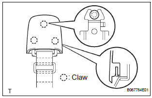
4. INSTALL POWER BACK DOOR TOUCH SENSOR LH
- Install the touch sensor with the clip.
- Using a torx driver (T25), tighten the 4 screws.
5. INSTALL POWER BACK DOOR TOUCH SENSOR RH
- Install the touch sensor with the clip.
- Using a torx driver (T25), tighten the 4 screws.
6. INSTALL BACK DOOR PULL STRAP
- Install the pull strap with the bolt.
Torque: 5.0 N*m (51 kgf*cm, 42 in.*lbf)
- Install the cover.
7. INSTALL BACK DOOR STAY BRACKET UPPER LH
- Install the bracket upper with the 2 bolts.
Torque: 12.5 N*m (112 kgf*cm, 9 ft.*lbf)
8. INSTALL POWER BACK DOOR DRIVE UNIT
- Install the drive unit with the 3 bolt.
Torque: 12.5 N*m (112 kgf*cm, 9 ft.*lbf)
- Reset the drive unit
 Adjustment
HINT:
On the RH side, use the same procedures as on the LH
side.
Since a centering bolt is used as door hinge mounting
bolts on the body side and the door side, the door cannot
be adjusted ...
 Power back door main switch
INSPECTION
1. INSPECT POWER BACK DOOR MAIN SWITCH
Inspect the resistance of the main switch.
Resistance
If the result is not as specified, replace the switch.
Apply battery voltage ...
Other materials:
Removal
1. DISCONNECT CABLE FROM NEGATIVE BATTERY
TERMINAL
2. REMOVE V-BANK COVER SUB-ASSEMBLY (See
page EM-28)
3. REMOVE PURGE VSV
(a) Disconnect the purge VSV connector.
(b) Disconnect the 2 purge line hoses from the purge
VSV.
(c) Remove the purge VSV from the air cleaner hose.
(d) R ...
Low pitched horn
COMPONENTS
REMOVAL
1. REMOVE FRONT BUMPER COVER
ET-3
2. REMOVE LOW PITCHED HORN
Disconnect the connector.
Remove the bolt and horn.
INSPECTION
1. INSPECT LOW PITCHED HORN
Apply battery voltage and check operation of the
horn, as shown in the table.
Stan ...
How to proceed with
troubleshooting
HINT:
Troubleshoot in accordance with the procedures on the
following pages.
1 VEHICLE BROUGHT TO WORKSHOP
2 CUSTOMER PROBLEM ANALYSIS CHECK AND SYMPTOM CHECK
3 PROBLEM SYMPTOMS TABLE
When problem is not listed on problem symptoms table,
proceed to A.
When problem is listed on pro ...
