Toyota Sienna Service Manual: Adjustment
HINT: On the RH side, use the same procedures as on the LH side.
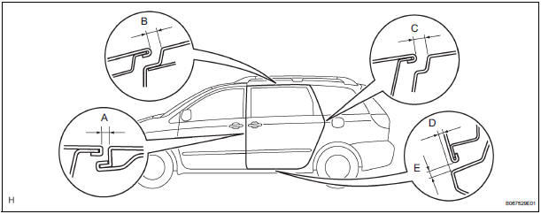
1. INSPECT SLIDE DOOR PANEL SUB-ASSEMBLY LH
- Check that the clearance is within the standard range.
Standard

2. ADJUST SLIDE DOOR PANEL SUB-ASSEMBLY LH

- Using the SST, horizontally and vertically adjust the
door by loosening the hinge center bolts.
SST 09812-00010, 09812-00020
- Tighten the hinge center bolts after the adjustment.
Torque: 31 N*m (306 kgf*cm, 23 ft.*lbf)
- Vertically adjust the front side of the door by loosening the roller lower bolts.
- Tighten the roller lower bolts after the adjustment.
Torque: 31 N*m (306 kgf*cm, 23 ft.*lbf)
- Horizontally adjust the front lower side of the door by loosening the roller lower bolts.
- Tighten the roller lower bolts after the adjustment.
Torque: 31 N*m (306 kgf*cm, 23 ft.*lbf)
- Horizontally adjust the front upper side of the door by loosening the roller upper bolts.
- Tighten the roller lower bolts after the adjustment.
Torque: 8.5 N*m (82 kgf*cm, 73 in.*lbf)
- Adjust the position the door lock striker by slightly loosening the striker mounting screws and hitting the striker with a plastic-faced hammer.
- Tighten the striker mounting screws after the
adjustment.
Torque: 23 N*m (235 kgf*cm, 17 ft.*lbf)
- Adjust the position the front lock striker by slightly loosening the striker mounting screws and hitting the striker with a plastic-faced hammer.
- Tighten the striker mounting screws after the
adjustment.
Torque: 23 N*m (235 kgf*cm, 17 ft.*lbf)
- Adjust the position of the down stopper by moving the male stopper, so that the male stopper can enter smoothly.
- Tighten the female stopper mounting bolts after the
adjustment.
Torque: 5.5 N*m (58 kgf*cm, 49 in.*lbf)
 Disassembly
1. REMOVE REAR DOOR WINDOW FRAME MOULDING
REAR LH (See page ET-31)
2. REMOVE REAR DOOR WINDOW FRAME MOULDING
SUB-ASSEMBLY LH (See page ET-32)
3. REMOVE SLIDE DOOR WINDOW GARNISH LH
Fully o ...
 Reassembly
1. INSTALL POWER SLIDE DOOR TOUCH SENSOR LH
Install the touch sensor with the 4 screws.
Connect the connector.
Fix the wire harness inside the door panel with the
clip.
2. INSTALL REA ...
Other materials:
Power back door main switch
INSPECTION
1. INSPECT POWER BACK DOOR MAIN SWITCH
Inspect the resistance of the main switch.
Resistance
If the result is not as specified, replace the switch.
Apply battery voltage and check the illuminates.
OK
HINT:
Whether the switch illuminates or not will not affect
th ...
Data list / active test
1. DATA LIST
HINT:
By the DATA LIST displayed by the intelligent tester, you
can read the value of the switch, sensor, actuator and so
on without removing any part. Reading the DATA LIST
as the first step in troubleshooting is one of the methods
to shorten the labor time.
Connect the ...
Brake Switch
DESCRIPTION
The stop light switch is a duplex system that transmits two signals: STP and
ST1-. These two signals are
used by the ECM to monitor whether or not the brake system is working properly.
If the signals, which
indicate the brake pedal is being depressed or released, are detected ...
