Toyota Sienna Service Manual: Disassembly
1. REMOVE REAR DOOR WINDOW FRAME MOULDING REAR LH (See page ET-31)
2. REMOVE REAR DOOR WINDOW FRAME MOULDING SUB-ASSEMBLY LH (See page ET-32)
3. REMOVE SLIDE DOOR WINDOW GARNISH LH
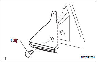
- Fully open the slide door window.
- Remove the glass run.
- Using a screwdriver, disengage the clip and remove
the garnish.
HINT: Tape the screwdriver tip before use.
- Using a screwdriver, disengage the 2 claws and
remove the weatherstrip inner from the garnish.
HINT: Tape the screwdriver tip before use.
4. REMOVE SIDE TRIM BOARD COVER REAR LH
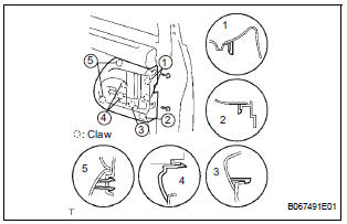
- Remove the 2 screws.
- Using a screwdriver, disengage the 8 claws and
remove the cover together with the window control
switch.
HINT: Tape the screwdriver tip before use.
- Remove the 2 screws and window control switch.
5. REMOVE REAR DOOR TRIM BOARD SUBASSEMBLY LH
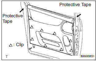
- Remove the screw.
- Using a screwdriver, disengage the 9 clips and remove the trim board.
HINT:
- Tape the screwdriver tip before use.
- In order to prevent the door panel from being damaged, cover the areas with protective tape as indicated by arrow marks in the illustration.
- Using a clip remover, remove the 6 clips and weatherstrip No. 2.
- Using a screwdriver, disengage the 11 claws and remove the weatherstrip inner from trim board.
HINT: Tape the screwdriver tip before use.
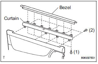
- w/ Sunshade: Remove the sunshade.
- Remove the 7 screws and sunshade bezel.
- Remove the 4 screws and curtain.
6. REMOVE SLIDE DOOR WINDOW ASSEMBLY LH
- w/ Sunshade: Remove the sun shade hook.
- Remove the bolt and window frame.
- Remove the bolt.
- Loosen the nut.
- Push the window frame rear lower in the direction indicated by the arrow mark in the illustration.
- Remove the 2 hole plugs.
- Move the window until the bolts appear in the service holes.
NOTICE:
- Do not damage the window.
- When the bolts are removed, the window may fall and become deformed.
- Remove the 2 bolts and window.
7. REMOVE REAR DOOR GLASS WEATHERSTRIP ASSEMBLY OUTER LH (See page ET-23)
8. REMOVE SLIDE DOOR ATTACHMENT CONTROL LH
- Remove the 2 screws, bolt and inside handle.
- Disconnect the connectors from the lock actuator, the power window regulator motor and lock release motor and power slide door lock.
- Disengage the control wires.
- Remove the 8 bolts and attachment control.
- Remove the nut and window frame rear lower.
NOTICE: When the nut is removed, the window frame may fall and become deformed.
HINT: Remove the window frame rear lower through the service hole.
- Remove the control rod.
- Remove the 3 bolts and lock remote control.
- Remove the 2 screws and lock actuator.
- Remove the 2 screws and lock release motor.
- Remove the 3 screws and power window regulator motor.
- Remove the half stop control lever and door lock control bellcrank.
- Remove the 4 bolts and the window regulator.
9. REMOVE REAR DOOR OUTSIDE HANDLE COVER LH
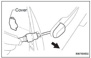
- Remove the outside handle hole cover.
- Using a torx socket wrench (T30), loosen the screw and remove the outside handle cover with the lock key cylinder installed
10. REMOVE REAR DOOR OUTSIDE HANDLE ASSEMBLY LH
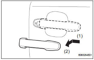
- Pushing and pulling the outside handle in the direction indicated by the arrow mark in the illustration, remove the outside handle.
- Remove the outside handle pads front and rear.
11. REMOVE REAR DOOR OUTSIDE HANDLE FRAME SUB-ASSEMBLY LH
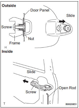
- Remove the open rod to the outside handle frame.
- Using a torx socket wrench (T30), loosen the screw.
- Slide the outside handle frame in the direction indicated by the arrow mark in the illustration and remove it.
HINT: Remove the outside handle frame through the service hole.
12. REMOVE POWER SLIDE DOOR CONTROL MOTOR AND CLUTCH
- Remove the 3 bolts from the upper part of the control motor and clutch.
- Remove the 2 clips and 4 bolts from the lower part of the control motor and clutch.
- Remove the control motor and clutch.
HINT: Remove the motor and clutch through the service hole.
13. REMOVE REAR DOOR STIFFENER CUSHION LH
- Remove the 2 screws, clip and stiffener cushion.
HINT: Remove the stiffener cushion through the service hole.
- Remove the 2 grommets and 2 clips.
14. REMOVE SLIDE DOOR LOCK ASSEMBLY FRONT LH
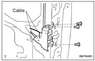
- Disconnect the 2 cables.
- Using a torx socket wrench (T30), remove the 3 screws and lock.
HINT: Remove the lock front through the service hole.
15. REMOVE POWER SLIDE DOOR LOCK ASSEMBLY LH
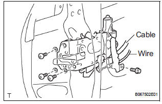
- Disconnect the cable and wire.
- Using a torx socket wrench (T30), remove the 3 screws.
- Remove the bolt and lock.
HINT: Remove the lock through the service hole.
16. REMOVE REAR DOOR WIRE SUB-ASSEMBLY LH
- Remove the 2 screws.
- Using a screwdriver, remove the 2 clips and wire.
HINT: Tape the screwdriver tip before use.
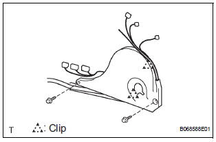
17. REMOVE POWER SLIDE DOOR ECU LH
- Remove the 2 screws and power slide door ECU with the warning buzzer.
- Disengage the claw and remove the warning buzzer.
18. REMOVE POWER SLIDE DOOR TOUCH SENSOR LH
- Disconnect the connector.
- Remove the 5 screws and touch sensor.
 Removal
HINT:
On the RH side, use the same procedures as on the LH side.
1. REMOVE SLIDE DOOR
Remove the rear door scuff plate (See page IR-7).
Remove the back door scuff plate (See page ED-
214 ...
 Adjustment
HINT:
On the RH side, use the same procedures as on the LH side.
1. INSPECT SLIDE DOOR PANEL SUB-ASSEMBLY LH
Check that the clearance is within the standard
range.
Standard
2. ADJUST ...
Other materials:
How to proceed with
troubleshooting
HINT:
Use the following procedures to troubleshoot the dynamic
laser cruise control system.
*: Use the intelligent tester
1 VEHICLE BROUGHT TO WORKSHOP
2 CUSTOMER PROBLEM ANALYSIS
3 PROBLEM SYMPTOM CONFIRMATION
Result
SYMPTOM SIMULATION
4 INSPECT BATTERY VOLTAGE
Stan ...
Dinghy towing
Your vehicle is not designed to be dinghy towed (with 4 wheels
on the ground) behind a motor home.
NOTICETo avoid serious damage to your vehicle
Do not tow your vehicle with four wheels
on the ground.
To prevent causing serious damage to the transaxle and Active
Torque ...
Reassembly
1. INSTALL REAR SEAT STAY SUB-ASSEMBLY
Install the rear seat stay sub-assembly with the nut.
Torque: 5.5 N*m (56 kgf*cm, 49 in.*lbf)
2. INSTALL NO. 2 SEAT CUSHION SPRING ASSEMBLY
LH
3. INSTALL LOCUS CABLE LH
Install the locus cable LH with the nut.
Torque: 5.5 N*m (56 kg ...
