
Toyota Sienna Service Manual: Airbag ECU Communication Stop
DTC B1281 Airbag ECU Communication Stop
DESCRIPTION
DTC B1281 is output when communication between the airbag ECU and the multiplex network gateway ECU stops for more than 10 seconds.
|
DTC No. |
DTC Detection Condition |
Trouble Area |
|
B1281 |
Airbag ECU communication stops |
|
WIRING DIAGRAM
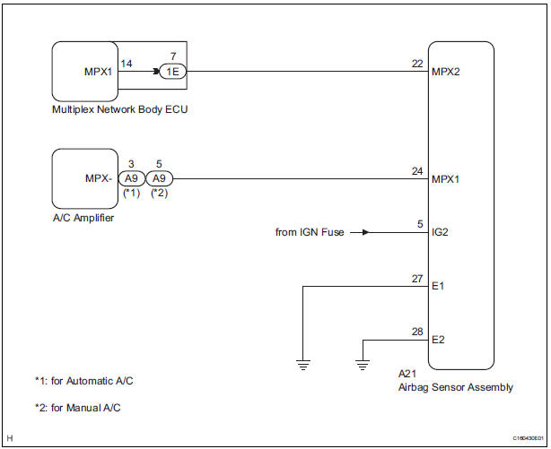
INSPECTION PROCEDURE
1 CHECK HARNESS AND CONNECTOR (AIRBAG SENSOR ASSEMBLY - BATTERY)
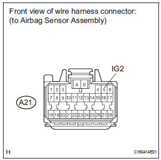
- Disconnect the A21 ECU connector.
- Measure the voltage according to the value(s) in the table below.
Standard voltage

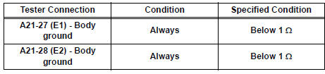
2 CHECK HARNESS AND CONNECTOR (AIRBAG SENSOR ASSEMBLY - GROUND)
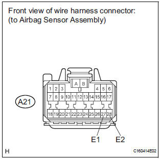
- Measure the resistance according to the value(s) in the table below.
Standard resistance
3 CHECK COMMUNICATION LINE
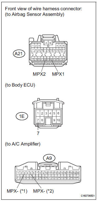
- Disconnect the 1E and A9 ECU connectors.
- Measure the resistance according to the value(s) in the table below.
Standard resistance
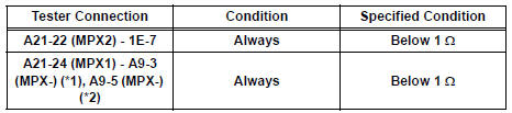
HINT:
*1: for Automatic A/C
*2: for Manual A/C
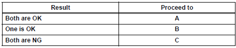
Result
REPLACE AIRBAG SENSOR ASSEMBLY
 Power Seat ECU Communication Stop
DTC B1272 Power Seat ECU Communication Stop
DESCRIPTION
This DTC is detected when communication between the seat position control ECU
and the multiplex
network gateway ECU stops for more than 10 ...
 Back Door ECU Communication Stop
DTC B1287 Back Door ECU Communication Stop
DESCRIPTION
DTC B1287 is output when communication between the power back door ECU and
the multiplex network
gateway ECU stops for more than 10 seconds. ...
Other materials:
ABS Warning Light Remains ON
DESCRIPTION
If any of the following is detected, the ABS warning light remains on.
The skid control ECU connectors are disconnected from the skid control
ECU.
There is a malfunction in the skid control ECU internal circuit.
There is an open in the harness between the combination meter an ...
Data list / active test
1. USING INTELLIGENT TESTER
Connect the intelligent tester to the DLC3.
Monitor the ECU data by following the prompts on
the tester screen.
HINT:
The intelligent tester has a "Snapshot" function
which records the monitored data.
Refer to the intelligent tester o ...
Before refueling the vehicle
Close all the doors and windows, and turn the engine switch to the
“LOCK� position (vehicles without a smart key system) or off (vehicles
with a smart key system).
Confirm the type of fuel.
Fuel type
Fuel tank opening for unleaded gasoline
To help prevent incorrect fueling, your ve ...
