
Toyota Sienna Service Manual: Back Door ECU Communication Stop
DTC B1287 Back Door ECU Communication Stop
DESCRIPTION
DTC B1287 is output when communication between the power back door ECU and the multiplex network gateway ECU stops for more than 10 seconds.
|
DTC No. |
DTC Detection Condition |
Trouble Area |
|
B1287 |
Back door ECU communication stops |
|
WIRING DIAGRAM
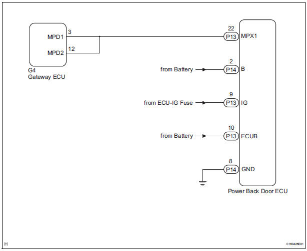
INSPECTION PROCEDURE
1 CHECK HARNESS AND CONNECTOR (POWER BACK DOOR ECU - BATTERY)
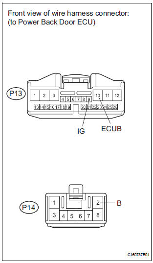
- Disconnect the P14 and P13 ECU connectors.
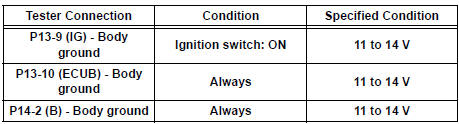
- Measure the voltage according to the value(s) in the table below.
Standard voltage
2 CHECK HARNESS AND CONNECTOR (POWER BACK DOOR ECU - GROUND)
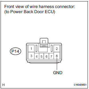
- Measure the resistance according to the value(s) in the table below.
Standard resistance

3 CHECK COMMUNICATION LINE
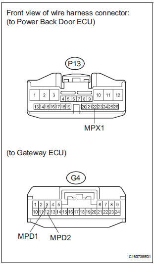
- Disconnect the G4 ECU connector.
- Measure the resistance according to the value(s) in the table below.
Standard resistance

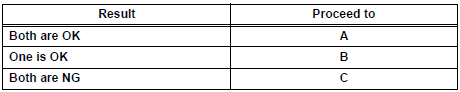
Result
REPLACE POWER BACK DOOR ECU
 Airbag ECU Communication Stop
DTC B1281 Airbag ECU Communication Stop
DESCRIPTION
DTC B1281 is output when communication between the airbag ECU and the
multiplex network gateway
ECU stops for more than 10 seconds.
...

Other materials:
Disassembly
1. REMOVE PARKING BRAKE PEDAL BRACKET PROTECTOR
(a) Using a flat-head screwdriver, disengage the 2
claws on the parking brake pedal bracket protector.
(b) Turning the parking brake pedal bracket protector
clockwise, remove the parking brake pedal bracket
protector from the parking brake ...
Rear Airbag Sensor LH Circuit Malfunction
DTC B1155/39 Rear Airbag Sensor LH Circuit Malfunction
DESCRIPTION
The rear airbag sensor LH circuit consists of the center airbag sensor
assembly and rear airbag sensor
LH.
If the center airbag sensor assembly receives signals from the rear airbag
sensor LH, it judges whether or
not the ...
If a warning light turns on
or a warning buzzer
sounds
Calmly perform the following actions if any of the warning lights
comes on or flashes. If a light comes on or flashes, but then
goes off, this does not necessarily indicate a malfunction in the
system. However, if this continues to occur, have the vehicle
inspected by your Toyota dealer.
Warnin ...
