Toyota Sienna Service Manual: Back Door Closer does not Operate
DESCRIPTION
The power back door ECU controls the back door closer system. In response to the signals output from the switches related to the back door lock, the back door latch activates the closer motor.
HINT: The back door closer system operates regardless of whether the power back door main switch is ON / OFF.
WIRING DIAGRAM
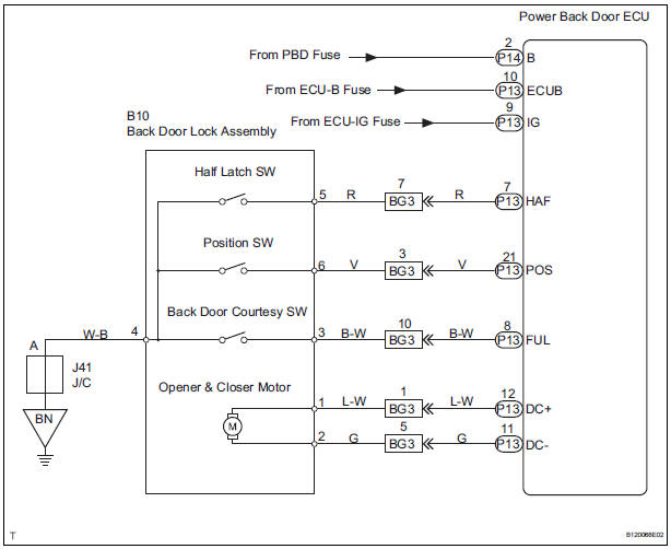
INSPECTION PROCEDURE
1 INSPECT BACK DOOR LOCK
- Check that the back door fully closes (fully locked) when the door is closed by hand.
2 POWER SOURCE RESET
- Disconnect the ECU-B fuse and reconnect it. 10 seconds later, check whether the back door closer is operational.
3 INSPECT BACK DOOR LOCK ASSEMBLY
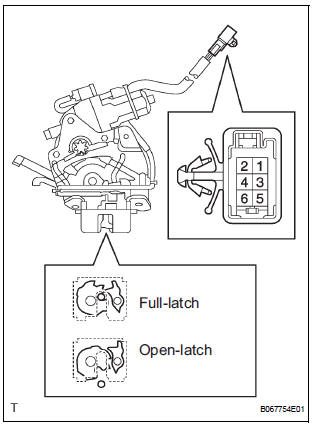
- Check operation of the door lock.
- Using a screwdriver, push the latch in order to put the back door lock in the locked condition (full-latch position).
- Connect the battery positive (+) lead to terminal 1
and the battery negative (-) lead to terminal 2. Then,
check operation of the latch.
OK: The latch turns to the open-latch position
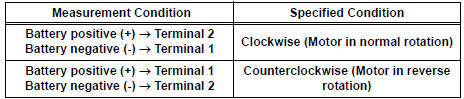
- Inspect motor operation when battery voltage is applied to the terminals.
OK
- Check the back door courtesy switch resistance.
- Check the resistance between the terminals of the courtesy switch.
Resistance
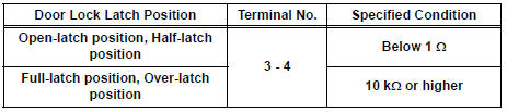
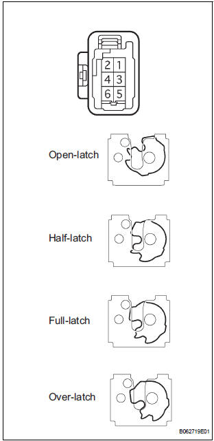
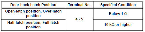
- Check the back door latch switch resistance.
- Check the resistance between the terminals of the latch switch.
Resistance
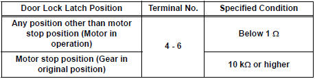
- Check the position switch resistance.
- Connect the battery positive (+) lead to connector terminal 1 and the negative (-) lead to connector terminal 2.
Resistance
4 CHECK WIRE HARNESS (BACK DOOR LOCK ASSEMBLY - POWER BACK DOOR ECU)
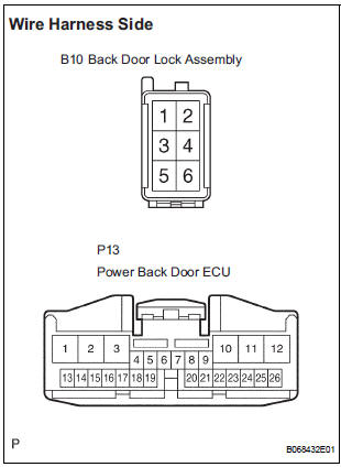
- Disconnect the B10 lock and P13 ECU connectors.
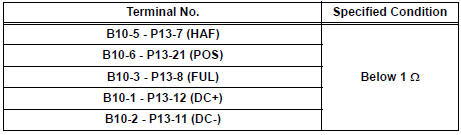
- Check the resistance between the wire harness side connectors.
Resistance (Check for open circuit)
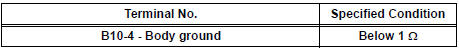
- Check the resistance between the B10 lock connector and body ground.
Resistance (Check for open circuit)
REPLACE POWER BACK DOOR ECU
 Back Door Closer Switch Malfunction
DTC B2215 Back Door Closer Switch Malfunction
DESCRIPTION
This DTC is output when a malfunction occurs in the position switch in the
back door. This position switch
detects if the back door is in ...
 Power back door system
PARTS LOCATION
...
Other materials:
Inspection
1. INSPECT OIL PUMP RELIEF VALVE
(a) Coat the relief valve with engine oil and check that it
falls smoothly into the valve hole under its own
weight.
If the valve does not fall smoothly, replace the relief
valve. If necessary, replace the oil pump assembly.
2. INSPECT OIL PUMP ROTOR SET
...
Vehicle Speed Signal Circuit between Stereo Component Amplifier and
Combination Meter
DESCRIPTION
This circuit is necessary for the ASL (Auto Sound Leveliser) built into the
stereo component amplifier.
Speed signals are received from the combination meter and used for the ASL.
The ASL function automatically adjusts the sound data in order to enable hearing
the clear audio ...
Front Occupant Classification Sensor RH Collision
Detection
DTC B1786 Front Occupant Classification Sensor RH Collision
Detection
DESCRIPTION
DTC B1786 is output when the occupant classification ECU receives a collision
detection signal sent by
the front occupant classification sensor RH if an accident occurs.
DTC B1786 is also output when the front ...
