Toyota Sienna Service Manual: Back door lock
INSPECTION
1. INSPECT BACK DOOR LOCK ASSEMBLY (W/O CLOSER)
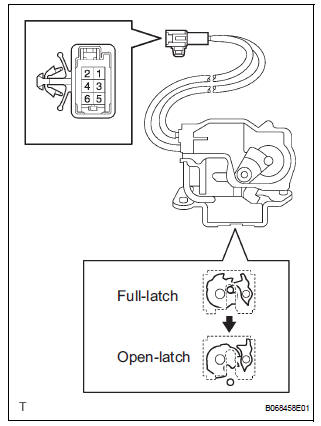
- Check operation of the door lock.
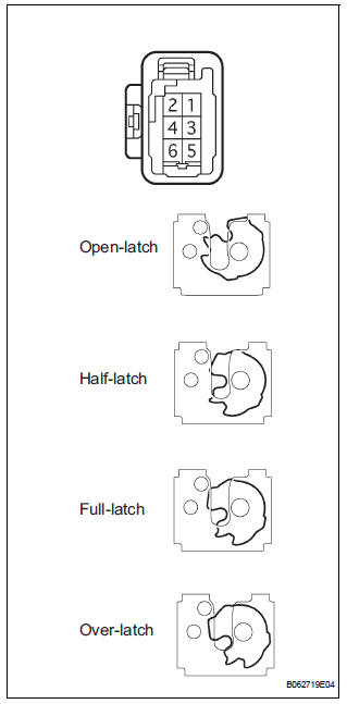
- Using a screwdriver, push the latch in order to put the back door lock in the locked condition (full-latch position).
- Connect the battery positive (+) lead to terminal
3 and the battery negative (-) lead to terminal 1.
Then, check operation of the latch.
Standard: The latch turns to the open-latch position If operation is not as specified, replace the door lock assembly.
- Inspect motor operation when battery voltage is applied to the terminals.
Standard
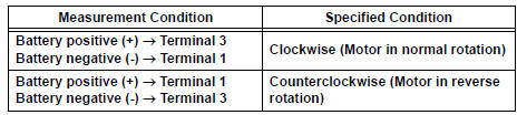
If operation is not as specified, replace the door lock assembly.
- Check the back door courtesy switch resistance.
- Check the resistance between the terminals of the courtesy switch.
Standard resistance
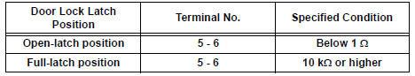
If the result is not as specified, replace the door lock assembly.
2. INSPECT BACK DOOR LOCK ASSEMBLY (W/ CLOSER)
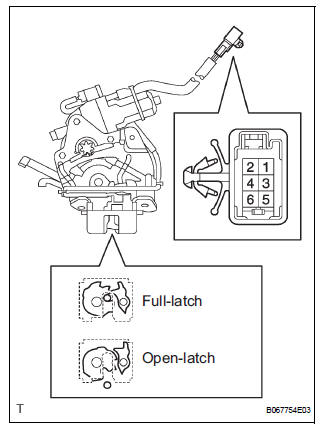
- Check operation of the door lock.
- Using a screwdriver, push the latch in order to put the back door lock in the locked condition (full-latch position).
- Connect the battery positive (+) lead to terminal
1 and the battery negative (-) lead to terminal 2.
Then, check operation of the latch.
Standard: The latch turns to the open-latch position
- Inspect motor operation when battery voltage is applied to the terminals.
Standard
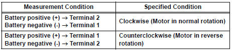
HINT: If operation is not as specified, replace the door lock assembly.
- Measure the resistance according to the value(s) in the table below.
Standard resistance (Courtesy switch)
HINT: If the result is not as specified, replace the door lock assembly.
- Measure the resistance according to the value(s) in the table below.
Standard resistance (Back door latch switch)
HINT: If the result is not as specified, replace the door lock assembly.
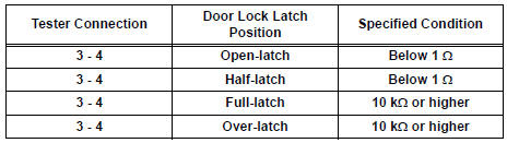
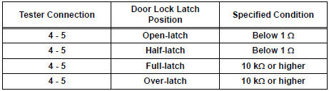
- Measure the resistance according to the value(s) in the table below.
Standard resistance (Position switch)
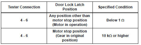
HINT: If the result is not as specified, replace the door lock assembly.
- Measure the resistance according to the value(s) in the table below.
- Full-latch: Connect the battery positive (+) lead to connector terminal 7 and the negative (-) lead to connector terminal 5.
Standard resistance
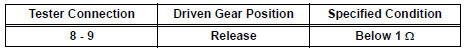
HINT: If the result is not as specified, replace the door lock assembly.
 Rear door lock
INSPECTION
1. INSPECT REAR DOOR LOCK ACTUATOR ASSEMBLY LH
Apply battery voltage to the door lock and check
operation of the motor.
OK
HINT:
If the result is not as specified, r ...
 Meter
Meter
...
Other materials:
Steering Pad Switch Circuit
DESCRIPTION
This circuit sends an operation signal from the steering pad switch to the
radio receiver.
If there is an open in the circuit, the navigation system cannot be operated
using the steering pad switch.
If there is a short in the circuit, the resulting condition is the same as if ...
Terminals of ECM
1. SFI SYSTEM
HINT:
The standard normal voltage between each pair of the
ECM terminals is shown in the table below. The
appropriate conditions for checking each pair of the
terminals are also indicated.
The check results should be compared with the standard
normal voltage for that pair of ...
Safety Connect services
Automatic Collision Notification
In case of either airbag deployment or severe rear-end collision, the
system is designed to automatically call the response center. The
responding agent receives the vehicle’s location and attempts to
speak with the vehicle occupants to assess the level of emer ...
