Toyota Sienna Service Manual: Camshaft Position "B" Actuator Circuit / Open
DTC P0013 Camshaft Position "B" Actuator Circuit / Open (Bank 1)
DTC P0023 Camshaft Position "B" Actuator Circuit / Open (Bank 2)
DESCRIPTION
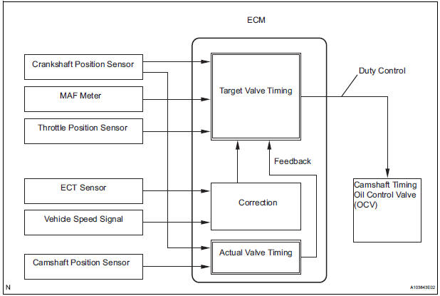
The Variable Valve Timing (VVT) system includes the ECM, OCV and VVT controller. The ECM sends a target duty-cycle control signal to the OCV. This control signal regulates the oil pressure supplied to the VVT controller. Camshaft timing control is performed according to engine operating conditions such as the intake air volume, throttle valve position and engine coolant temperature. The ECM controls the OCV, based on the signals transmitted by several sensors. The VVT controller regulates the exhaust camshaft angle using oil pressure through the OCV. As a result, the relative positions of the camshaft and crankshaft are optimized, the engine torque and fuel economy improve, and the exhaust emissions decrease under overall driving conditions. The ECM detects the actual exhaust valve timing using signals from the camshaft and crankshaft position sensors, and performs feedback control. This is how the target intake valve timing is verified by the ECM
|
DTC No. |
DTC Detection Condition |
Trouble Area |
| P0013 | Open or short in OCV for exhaust camshaft (bank 1) circuit (1 trip detection logic) |
|
| P0023 | Open or short in OCV for exhaust camshaft (bank 2) circuit (1 trip detection logic) |
|
MONITOR DESCRIPTION
The ECM optimizes the valve timing using the VVT system to control the exhaust camshaft. The VVT system includes the ECM, the OCV and the VVT controller. The ECM sends a target duty-cycle control signal to the OCV. This control signal regulates the oil pressure supplied to the VVT controller. The VVT controller can advance or retard the exhaust camshaft.
After the ECM sends the target duty-cycle signal to the OCV, the ECM monitors the OCV current to establish an actual duty-cycle. The ECM determines the existence of a malfunction and sets the DTC when the actual duty-cycle ratio varies from the target duty-cycle ratio.
MONITOR STRATEGY
TYPICAL ENABLING CONDITIONS
TYPICAL MALFUNCTION THRESHOLDS
COMPONENT OPERATING RANGE

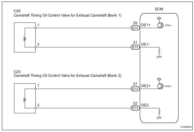
WIRING DIAGRAM
INSPECTION PROCEDURE
HINT:
- If DTC P0013 is displayed, check the exhaust camshaft circuit for the bank 1 VVT system.
- Bank 1 refers to the bank that includes cylinder No. 1.
- If DTC P0023 is displayed, check the exhaust camshaft circuit for the bank 2 VVT system.
- Bank 2 refers to the bank that does not include cylinder No. 1.
- Read freeze frame data using an intelligent tester. The ECM records vehicle and driving condition information as freeze frame data the moment a DTC is stored. When troubleshooting, freeze frame data can be helpful in determining whether the vehicle was running or stopped, whether the engine was warmed up or not, whether the air-fuel ratio was lean or rich, as well as other data recorded at the time of a malfunction.
1 PERFORM ACTIVE TEST BY INTELLIGENT TESTER (OPERATE OCV)
- Connect the intelligent tester to the DLC3.
- Start the engine and turn the tester on.
- Warm up the engine.
- Enter the following menus: DIAGNOSIS / ENHANCED OBD II / ACTIVE TEST / VVT CTRL B1 or VVT CTRL B2.
- Check the engine speed while operating the Oil Control Valve (OCV) using the tester.
OK

CHECK FOR INTERMITTENT PROBLEMS
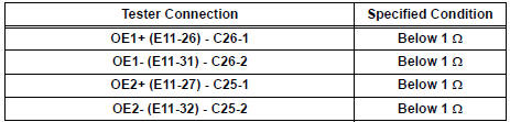
2 INSPECT CAMSHAFT TIMING OIL CONTROL VALVE ASSEMBLY
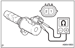
- Disconnect the C26 or C25 camshaft timing oil control valve (OCV) connector.
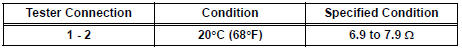
- Measure the resistance according to the value(s) in the table below.
Standard resistance
- Reconnect the OCV connector.
REPLACE CAMSHAFT TIMING OIL CONTROL VALVE ASSEMBLY
3 CHECK HARNESS AND CONNECTOR (OCV - ECM)
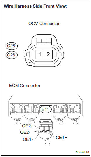
- Disconnect the C25 or C26 camshaft timing oil control valve (OCV) connector.
- Disconnect the E11 ECM connector.
- Measure the resistance according to the value(s) in the table below.
Standard resistance (Check for open)
Standard resistance (Check for short)
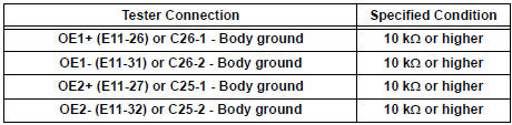
- Reconnect the ECM connector.
- Reconnect the OCV connector
REPLACE ECM
 Camshaft Position "A" - Timing Over-Advanced
DTC P0011 Camshaft Position "A" - Timing Over-Advanced
or System Performance (Bank 1)
DTC P0012 Camshaft Position "A" - Timing Over-Retarded
(Bank 1)
DTC P0021 Camshaft Positio ...
 Camshaft Position "B" - Timing Over-Advanced
DTC P0014 Camshaft Position "B" - Timing Over-Advanced
or System Performance (Bank 1)
DTC P0015 Camshaft Position "B" - Timing Over-Retarded
(Bank 1)
DTC P0024 Camshaft Positio ...
Other materials:
Evaporator temperature sensor
ON-VEHICLE INSPECTION
1. INSPECT A/C EVAPORATOR TEMPERATURE SENSOR
(a) Remove the A/C evaporator temperature sensor (A/
C thermistor).
(b) Disconnect the connector from the A/C evaporator
temperature sensor (A/C thermistor).
(c) Measure the resistance according to the value(s) in
the ...
Terminals of ECU
1. MULTIPLEX NETWORK GATEWAY ECU
Disconnect the G4 ECU connector.
Measure the voltage between the specified
terminals on the wire harness side connector.
If the result is not as specified, there may be a
malfunction on the wire harness side.
Measure the resistance between ...
Intake Air Temperature Sensor Gradient Too High
DESCRIPTION
The Intake Air Temperature (IAT) sensor, mounted on the Mass Air Flow (MAF)
meter, monitors the IAT.
The IAT sensor has a built-in thermistor with a resistance that varies according
to the temperature of the
intake air. When the IAT becomes low, the resistance of the the ...
