Toyota Sienna Service Manual: Installation
1. INSTALL TIRE PRESSURE WARNING ECU
(a) Connect the connector to the tire pressure warning ECU.
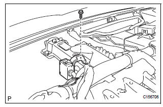
(b) Install the tire pressure warning ECU with the screw.
2. INSTALL INSTRUMENT PANEL SAFETY PAD SUBASSEMBLY
HINT: Refer to the instructions for INSTALLATION of the instrument panel safety pad (See page IP-14)
3. CONNECT CABLE TO BATTERY NEGATIVE TERMINAL
4. REGISTER TRANSMITTER ID
HINT: See page TW-20.
5. INSPECT TIRE PRESSURE WARNING SYSTEM
HINT: See page TW-25.
6. INITIALIZE SYSTEM
NOTICE:
- Be sure to register the transmitter IDs of all tires in the ECU before initialization.
- Be sure to inflate all tires to the proper inflation pressure before initialization.
HINT: See page TW-23.
 Removal
NOTICE:
Before removing the tire pressure warning ECU, read the
registered transmitter IDs of all wheels and write them
down to use for re-registration of transmitter IDs (See
page TW-20).
1. DIS ...
 Tire pressure warning reset switch
COMPONENTS
...
Other materials:
Removal
1. Drain automatic transaxle fluid
(a) Remove the drain plug, gasket and drain ATF.
(b) Install a new gasket and the drain plug.
Torque: 49 N*m (500 kgf*cm, 36 ft.*lbf)
2. Drain transfer oil (for 4wd)
Hint:
(see page tf-8)
3. Remove front wheel
4. REMOVE FRONT AXLE HUB LH NUT
(a) Us ...
Short in Front Passenger Side Squib 2nd Step
Circuit
DTC B1185/57 Short in Front Passenger Side Squib 2nd Step
Circuit
DESCRIPTION
The front passenger side squib 2nd step circuit consists of the center airbag
sensor assembly and the
front passenger airbag assembly.
The circuit instructs the SRS to deploy when deployment conditions are met.
...
Child restraint systems with a top tether strap (second seat)
Secure the child restraint system
using the seat belt or
LATCH anchors, and adjust the
head restraint to the uppermost
position.
*: Ottoman seat only
Latch the hook onto the anchor
bracket and tighten the top
tether strap.
Make sure the top tether strap is
secure ...
