Toyota Sienna Service Manual: Wiper switch
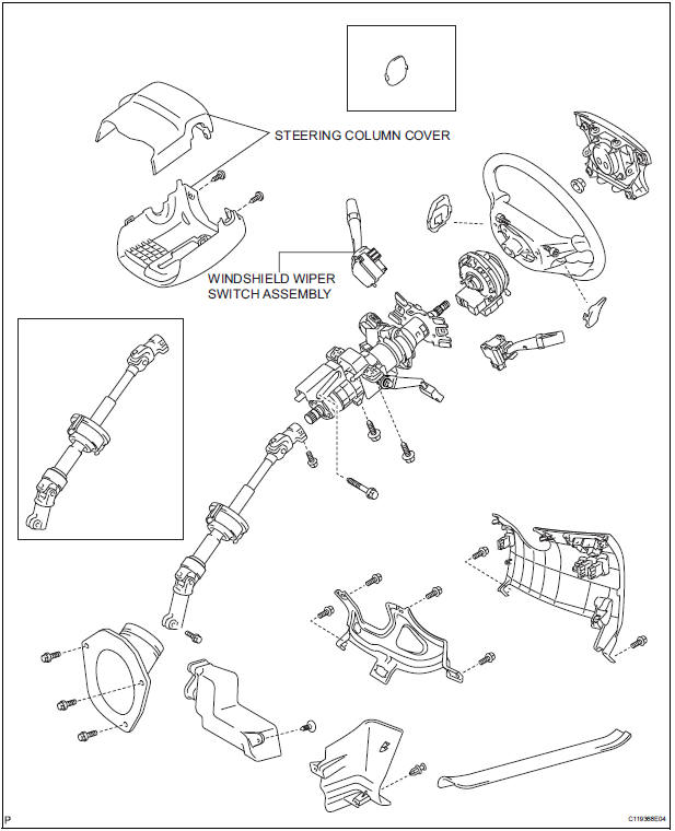
COMPONENTS
REMOVAL
1. REMOVE STEERING COLUMN COVER
2. REMOVE WINDSHIELD WIPER SWITCH ASSEMBLY
- Disconnect the connector.
- Using a screwdriver, disengage the claw and pull out the windshield wiper switch assembly.
NOTICE: The claw will be broken if pressed hard.
HINT: Tape up the screwdriver tip before use.
INSPECTION
1. INSPECT WINDSHIELD WIPER SWITCH ASSEMBLY
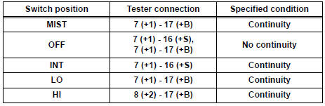
- Continuity Check
- Check the continuity between each of the terminals of the connector.
Standard:
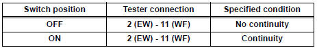
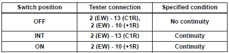
Front Wiper Switch
Front Washer Switch
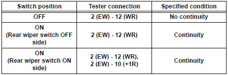
Rear Wiper Switch
Rear Washer Switch
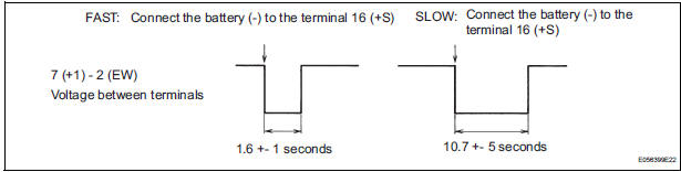
- Intermittent Operation Check
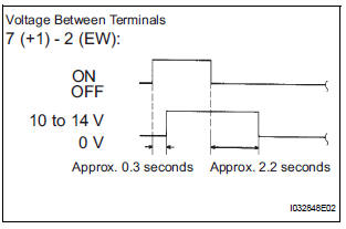
- Connect the voltmeter (+) terminal to the terminal 7 (+1) of the connector, the voltmeter (-) terminal to the terminal 2 (EW) of the connector.
- Connect the battery (+) to the terminal 17 (+B) of the connector, the battery (-) to the terminal 2 (EW) and the terminal 16 (+S) of the connector.
- Turn the wiper switch into the INT position.
- Connect the battery (+) to the terminal 16 (+S) of the connector for 5 seconds.
- Connect the battery (-) to the terminal 16 (+S) of the connector. Operate the intermittent wiper relay and check voltage between the terminal 7 (+1) and the terminal 2 (EW).
- Operation Check (Front Wiper)
- Turn the wiper switch into the OFF position.
- Connect the battery (+) to the terminal 17 (+B) of the connector, the battery (-) to the terminal 16 (+S) and 2 (EW) of the connector.
- Connect the voltmeter (+) terminal to the terminal 7 (+1) of the connector, the voltmeter (-) terminal to the terminal 2 (EW) of the connector. Turn the washer switch ON and OFF and check voltage between the terminal 7 (+1) and the terminal 2 (EW).
INSTALLATION
1. INSTALL WINDSHIELD WIPER SWITCH ASSEMBLY
2. REMOVE STEERING COLUMN COVER
 Rear wiper rubber
COMPONENTS
REMOVAL
1. REMOVE REAR WIPER BLADE ASSEMBLY
Remove the rear wiper arm head cap from the rear
wiper arm.
Raise the rear wiper blade to the position as shown
i ...
 Front washer motor
ON-VEHICLE INSPECTION
1. INSPECT FRONT WASHER MOTOR
Operation Check
Pour the water into the washer jar with the
windshield washer motor and pump installed to
the washer ...
Other materials:
Precaution
Keep in mind the following points when inspecting the
dynamic laser cruise control system.
As there is a limitation on the vehicle-to-vehicle distance
controlling capability, do not overly rely on the dynamic
laser cruise control system.
Do not neglect to pay constant attentio ...
Removal
1. DISCONNECT CABLE FROM NEGATIVE BATTERY
TERMINAL
2. REMOVE AIR FUEL RATIO SENSOR (for Bank 2
Sensor 1)
(a) Disconnect the sensor connector.
(b) Using SST, remove the sensor from the exhaust
manifold.
SST 09224-00010
3. REMOVE FRONT EXHAUST PIPE ASSEMBLY
(a) Disconnect the heat ...
No Master/ Connection Check Error
DTC 01-D6 No Master
DTC 01-D7 Connection Check Error
DESCRIPTION
HINT:
*1: Even if no fault is present, this trouble code may be stored
depending on the battery condition or
engine start voltage.
*2: When 210 seconds have elapsed after disconnecting the power
supply ...
