Toyota Sienna Service Manual: Check mode procedure
1. LIST OF OPERATION METHODS
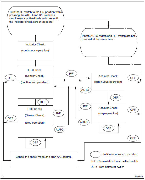
By operating each of the A/C control switches as shown in the diagram below, it is possible to enter the diagnosis check mode.
 Dtc check / clear
1. DTC CHECK (SENSOR CHECK)
(a) After the indicator check is completed, the system
enters the DTC check mode automatically.
(b) Read the codes displayed on the panel. Refer to the
list of co ...
 Data list / active test
1. DATA LIST
HINT:
Using the intelligent tester to read the Data List allows
the values or states of switches, sensors, actuators and
other items to be read without removing any parts. This
non-i ...
Other materials:
Using a Bluetooth®
Phone
The hands-free system is a function that allows you to use your
cellular phone without touching it.
This system supports Bluetooth®. Bluetooth® is a wireless data
system that allows the cellular phone to wirelessly connect to
the hands-free system and make/receive calls.
Before making a p ...
Terminals of ecu
1. A/C AMPLIFIER
HINT:
Check from the rear of the connector while it is
connected to the A/C amplifier.
(a) Waveform 1:
(b) Waveform 2: ...
Removal
1. RECOVER REFRIGERANT FROM REFRIGERATION
SYSTEM (See page AC-172)
2. REMOVE FRONT WHEEL RH
3. REMOVE FRONT FENDER APRON SEAL RH (See
page EM-26)
4. REMOVE V-RIBBED BELT (See page EM-6)
5. REMOVE RADIATOR AND FAN ASSEMBLY
(See page CO-28)
6. DISCONNECT DISCHARGE HOSE SUB-ASSEMBLY
(a) Re ...
