Toyota Sienna Service Manual: Dtc check / clear
1. DTC CHECK (SENSOR CHECK)
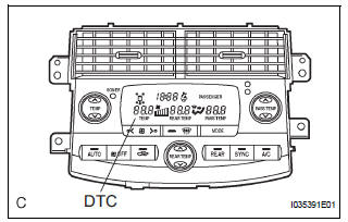
(a) After the indicator check is completed, the system enters the DTC check mode automatically.
(b) Read the codes displayed on the panel. Refer to the list of codes (See page AC-19) when reading the codes. (Trouble codes are output at the temperature display.)
(c) If the slower display is desired, press the DEF switch and change it to the step operation. Each time the DEF switch is pressed, the display changes by 1 step.
2. CLEARING DTC
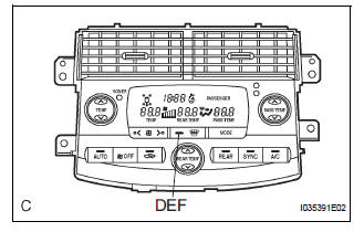
(a) To clear diagnostic trouble codes, there are 2 ways.
(1) During sensor check, press the "DEF" switch and "A/C" switch at the same time.
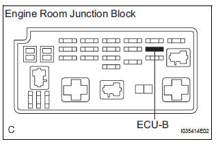
(2) Remove the ECU-B fuse in the engine room junction block for 20 seconds or longer to clear the DTC memory.
 Diagnosis system
1. CHECK DLC3
(a) The vehicle's ECM uses the ISO 15765-4 for
communication. The terminal arrangement of the
DLC3 complies with SAE J1962 and matches the
ISO 15765-4 format.
HINT:
Connect the ...
 Check mode procedure
1. LIST OF OPERATION METHODS
By operating each of the A/C control switches as shown
in the diagram below, it is possible to enter the diagnosis
check mode.
...
Other materials:
Shift position purpose
*1: Shifting to the D position allows the system to select a gear suitable
for
the driving conditions. Setting the shift lever to the D position is recommended
for normal driving.
*2: Selecting shift ranges using S mode restricts the upper limit of the
possible
gear ranges, controls en ...
Reassembly
1. INSTALL SHOCK ABSORBER ASSEMBLY FRONT LH
2. INSTALL FRONT COIL SPRING INSULATOR LOWER
LH
(a) Install the front coil spring insulator lower LH onto
the shock absorber assembly front LH.
3. INSTALL FRONT SPRING BUMPER LH
(a) Install the front spring bumper LH to the piston rod.
4. INSTALL FR ...
Rear view monitor system precautions
Area displayed on screen
The rear view monitor system
displays an image of the view
from the bumper of the rear
area of the vehicle.
The image on the rear view monitor system can be adjusted.
The area displayed on the
screen may vary according to
vehicle orientation conditions.
...
