Toyota Sienna Service Manual: Removal
1. RECOVER REFRIGERANT FROM REFRIGERATION SYSTEM (See page AC-172)
2. REMOVE FRONT WHEEL RH
3. REMOVE FRONT FENDER APRON SEAL RH (See page EM-26)
4. REMOVE V-RIBBED BELT (See page EM-6)
5. REMOVE RADIATOR AND FAN ASSEMBLY (See page CO-28)
6. DISCONNECT DISCHARGE HOSE SUB-ASSEMBLY

(a) Remove the bolt and disconnect the discharge hose sub-assembly from the compressor and magnetic clutch.
(b) Remove the O-ring from the discharge hose subassembly.
NOTICE: Seal the openings of the disconnected parts using vinyl tape to prevent entry of moisture and foreign matter.
7. DISCONNECT SUCTION HOSE SUB-ASSEMBLY

(a) Remove the bolt and disconnect the suction hose sub-assembly from the compressor and magnetic clutch.
(b) Remove the O-ring from the suction hose subassembly.
NOTICE: Seal the openings of the disconnected parts using vinyl tape to prevent entry of moisture and foreign matter.
8. REMOVE COMPRESSOR AND MAGNETIC CLUTCH
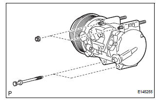
(a) Disconnect the connector.
(b) Release the 2 clamps and wire harness.
(c) Remove the 2 bolts and 2 nuts.
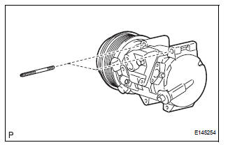
(d) Using a "TORX" socket wrench (E8), remove the 2 stud bolts and the compressor and magnetic clutch.
 Compressor and magnetic clutch
COMPONENTS
...
 Disassembly
1. REMOVE MAGNETIC CLUTCH ASSEMBLY
(a) Place the compressor and magnetic clutch in a vise.
(b) Using locking pliers, hold the magnetic clutch hub.
(c) Remove the bolt, magnetic clutch hub, and
...
Other materials:
Rear view monitor
system
The rear view monitor system assists the driver by displaying an
image of the view behind the vehicle and guide lines while backing
up, for example while parking.
The screen illustrations used in this text are intended as examples,
and may differ from the image that is actually displayed on the
...
Initialization
1. RESET SLIDING ROOF MOTOR
If the AUTO operation function does not operate,
reset the sliding roof motor using any of the
following methods.
Press the sliding roof switch on the TILT UP side
and hold it until the sliding roof motor stops.
Then release the switch and leave it untou ...
Diagnosis system
1. CHECK DLC3
The vehicle's ECU uses ISO 15765-4 for
communication protocol. The terminal arrangement
of the DLC3 complies with SAE J1962 and matches
the ISO 15765-4 format.
NOTICE:
*: Before measuring the resistance, leave the
vehicle as is for at least 1 minute and do not
...
