Toyota Sienna Service Manual: Check mode procedure
HINT: Check mode has a higher sensitivity to malfunctions and can detect malfunction that normal mode cannot detect. Check mode can also detect all the malfunctions that normal mode can detect. In check mode, DTCs are detected with 1-trip detection logic.
Dtc check (check mode)
HINT: Intelligent tester only: Compared to the normal mode, the check mode is more sensitive for detecting malfunctions.
Furthermore, the same diagnostic items which are detected in the normal mode can also be detected in the check mode.
(a) Procedure for Check Mode using the intelligent tester.
(1) Check the initial conditions.
- Battery positive voltage 11 V or more
- Throttle valve fully closed
- Transaxle in the P or N position
- A/C switch is off
(2) Turn the ignition switch off.
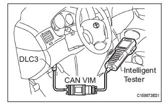
(3) Connect the intelligent tester together with the CAN VIM (controller area network vehicle interface module) to the DLC3.
(4) Turn the ignition switch to ON position and turn the intelligent tester main switch on.
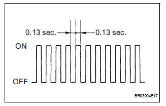
(5) Select the item "DIAGNOSIS/ENHANCED OBD II/CHECK MODE" (Check that the MIL flashes).
| NOTICE: All DTCs and freeze frame data recorded will be erased if: 1) the intelligent tester is used to change the ECM from normal mode to check mode or vice-versa; or 2) during check mode, the ignition switch is turned from the ON to ACC position or turned OFF |
(6) Start the engine (the MIL goes off after the engine starts).
(7) Perform "MONITOR DRIVE PATTERN" for the ECT test (See page AX-17). (Or, simulate the conditions of the malfunction described by the customer).
| NOTICE: Leave the ignition switch in the ON position until you have checked the DTCs, etc. |
(8) After simulating malfunction conditions, use the intelligent tester diagnosis selector to check the DTCs and freeze frame data, etc.
(9) When you use intelligent tester: Select the item "DIAGNOSIS / ENHANCED OBD II / DTC INFO / CURRENT CODES".
(10)After checking the DTC, inspect the applicable circuit.
(11)(See page AX-35) to confirm the details of the DTCs.
 Dtc check / clear
1. DTC CHECK (NORMAL MODE)
NOTICE:
When the diagnostic system is switched from the
normal mode to the check mode, all the DTCs and
freeze frame data recorded in the normal mode will
...
 Dtc clear
(A) when using the obd ii scan tool or intelligent
tester: clearing the dtcs.
(1) Connect the intelligent tester together with the
CAN VIM (controller area network vehicle
interface module) to the ...
Other materials:
Hitch
Trailer hitch assemblies have different weight capacities. Toyota recommends
the use of Toyota hitch/bracket for your vehicle. For details,
contact your Toyota dealer.
If you wish to install a trailer hitch, contact your Toyota
dealer.
Use only a hitch that conforms to the gross trailer w ...
Removal
1. REMOVE NO. 1 REAR SEAT OUTER BELT
ASSEMBLY (for 8-Passenger)
HINT:
Refer to the instructions for disassembly of the rear No .1 seat assembly (for
center seat).
Remove the rear seatback board.
Remove the rear seat shoulder belt cover.
Remove the 2 bolts, 2 nuts and N ...
Rear Blower Motor Circuit
DESCRIPTION
Power to the rear blower motor is supplied from the battery via the RR A/C
relay.
The rear blower motor speed level varies between 0 and 31 based on the voltage
difference measured
between the terminals of the motor.
The voltage difference measured between the terminals of th ...
