Toyota Sienna Service Manual: Dtc check / clear
1. DTC CHECK (NORMAL MODE)
| NOTICE: When the diagnostic system is switched from the normal mode to the check mode, all the DTCs and freeze frame data recorded in the normal mode will be erased. So before switching modes, always check the DTCs and freeze frame data, and note them down. |
(a) Checking DTCs using the OBD II scan tool or intelligent tester.
(1) Turn the ignition switch off.
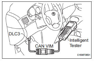
(2) Connect the intelligent tester together with the CAN VIM (controller area network vehicle interface module) to the DLC3.
(3) Turn the ignition switch to the ON position and turn the OBD II scan tool or the intelligent tester main switch on.
(4) Select the item "DIAGNOSIS / ENHANCED OBD II / DTC INFO / CURRENT CODES".
(5) Use the OBD II scan tool or intelligent tester to check the DTCs and freeze frame data and note them down (For operating instructions, see the OBD II scan tool's instruction book).
| NOTICE: When simulating symptoms with an OBD II scan tool (excluding intelligent tester) to check the DTCs, use the normal mode. For codes on the DTCs chart which are subject to "2 trip detection logic", |
Turn the ignition switch off after the symptom is simulated once. Then repeat the simulation process again. When the problem has been simulated twice, the MIL illuminates and the DTCs are recorded in the ECM.
2. DTC CLEAR
(a) When using the OBD II scan tool or intelligent tester: Clearing the DTCs.
(1) Connect the intelligent tester together with the CAN VIM (controller area network vehicle interface module) to the DLC3.
(2) Turn the ignition switch to the ON position and turn the OBD II scan tool or the intelligent tester main switch on.
(3) Select the item "DIAGNOSIS / ENHANCED OBD II / DTC INFO / CLEAR CODES [YES] button".
HINT: When operating the OBD II scan tool (complying with SAE J1978) or intelligent tester to erase the codes, the DTCs and freeze frame data will be erased. (See the OBD II scan tool's instruction book for operating instructions.)
(b) When not using the OBD II scan tool or intelligent tester: Clearing the DTCs.
(1) Disconnect the battery terminal or remove the EFI and ETCS fuses from the engine room J/B for 60 seconds or more. However, if you disconnect the battery terminal, perform do the "INITIALIZE" procedure.
 Diagnosis system
1. DESCRIPTION
(a) When troubleshooting OBD II vehicles, the only
difference from the usual troubleshooting procedure
is to connect an OBD II scan tool complying with
SAE J1987 or a intelligen ...
 Check mode procedure
HINT:
Check mode has a higher sensitivity to malfunctions and can
detect malfunction that normal mode cannot detect. Check
mode can also detect all the malfunctions that normal mode
can detect. In ...
Other materials:
Route cannot be Calculated
INSPECTION PROCEDURE
1 CHECK MAP DISC
Check that the map disc is not deformed or cracked.
OK:
No deformations or cracks on map disc.
2 SET DESTINATION
Set another destination and check if the system can
calculate the route correctly.
OK:
Route can be correctly calculated.
NO ...
Fold Seat Switch Circuit
DESCRIPTION
When the fold seat switch is operated, a switch operation signal is sent to
the fold seat control ECU. The
ECU receives switch operation signals from each switch and activates the folding
motor, reclining motor,
and release actuator.
WIRING DIAGRAM
INSPECTION PROCEDURE
1 IN ...
Operating Light Control Rheostat does not Change Light Brightness
DESCRIPTION
The meter CPU receives signals for adjusting illumination on the meter from
this circuit. The meter CPU
detects the illumination level selected by the user according to the position of
the rheostat knob.
WIRING DIAGRAM
INSPECTION PROCEDURE
1 READ VALUE OF INTELLIGENT TESTER ...
