Toyota Sienna Service Manual: Clearance warning ECU
COMPONENTS
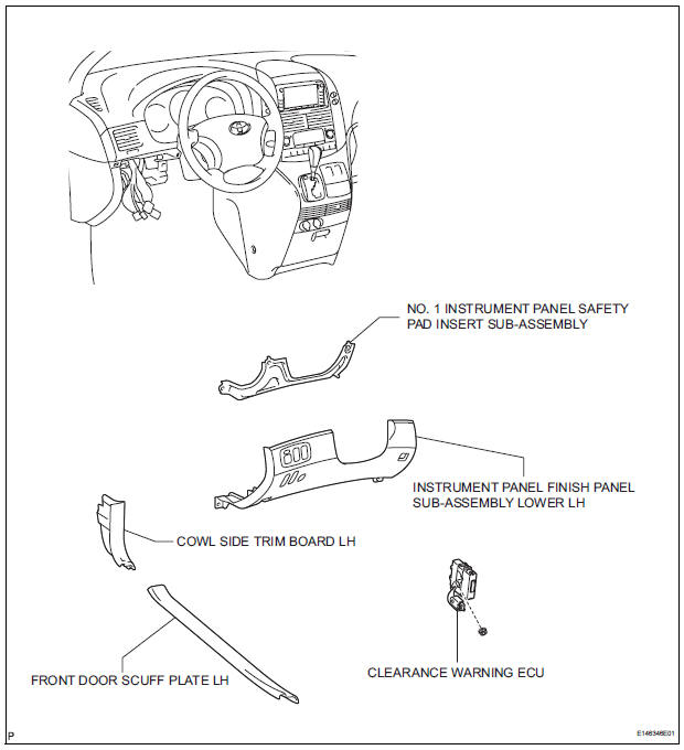
REMOVAL
1. REMOVE FRONT DOOR SCUFF PLATE LH
2. REMOVE COWL SIDE TRIM BOARD LH
3. REMOVE INSTRUMENT PANEL FINISH PANEL SUBASSEMBLY LOWER LH
4. REMOVE NO. 1 INSTRUMENT PANEL SAFETY PAD INSERT SUB-ASSEMBLY
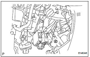
5. REMOVE CLEARANCE WARNING ECU
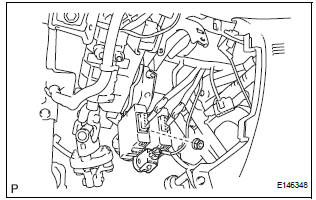
- Disconnect each connector.
- Remove the nut and clearance warning ECU.
INSTALLATION
1. INSTALL CLEARANCE WARNING ECU
- Install the clearance warning ECU with the nut.
- Connect each connector.
2. INSTALL NO. 1 INSTRUMENT PANEL SAFETY PAD INSERT SUB-ASSEMBLY
3. INSTALL INSTRUMENT PANEL FINISH PANEL SUBASSEMBLY LOWER LH
4. INSTALL COWL SIDE TRIM BOARD LH
5. INSTALL FRONT DOOR SCUFF PLATE LH
 Display Signal Circuit between Radio and Navigation Assembly and
Television Camera Assembly
Display Signal Circuit between Radio and Navigation Assembly and
Television Camera Assembly
DESCRIPTION
This is the display signal circuit of the television camera assembly.
WIRING DIAGRAM
INSPECTION PROCEDURE
1 CHECK HARNESS AND CONNECTOR (RADIO AND NAVIGATION ASSEMBLY - TELEVISION ...
 No. 1 Ultrasonic sensor
COMPONENTS
REMOVAL
1. REMOVE FRONT FENDER LINER LH
2. REMOVE FRONT FENDER LINER RH
3. REMOVE FRONT BUMPER COVER
4. REMOVE REAR BUMPER COVER (2)
5. REMOVE NO. 1 ULTRASONIC SENSOR RETAINER
...
Other materials:
Short in CAN Bus Lines
DESCRIPTION
The CAN bus wires are considered to be shorted when the resistance between
terminals 6 (CANH) and
14 (CANL) of the DLC3 is below 54 Ω.
Symptom
Trouble Area
Resistance between terminals 6 (CANH) and 14 (CANL) of the DLC3
is below 54 Ω.
...
DSP Error/ DSP Error
DTC 62-78 DSP Error
DTC 63-78 DSP Error
DESCRIPTION
INSPECTION PROCEDURE
HINT:
After the inspection is completed, clear the DTCs.
NOTICE:
These codes may be output even if there is no malfunction.
If these codes are output frequently, replace the radio receiver.
1 CLEA ...
Installation
1. INSTALL AMPLIFIER ANTENNA ASSEMBLY
Engage the 16 clamps to install the amplifier
antenna assembly.
Install the 3 bolts.
Connect the connectors.
2. INSTALL ROOF HEADLINING ASSEMBLY
3. INSTALL ANTENNA ASSEMBLY WITH HOLDER
Install the antenna assembly ...
