Toyota Sienna Service Manual: No. 1 Ultrasonic sensor
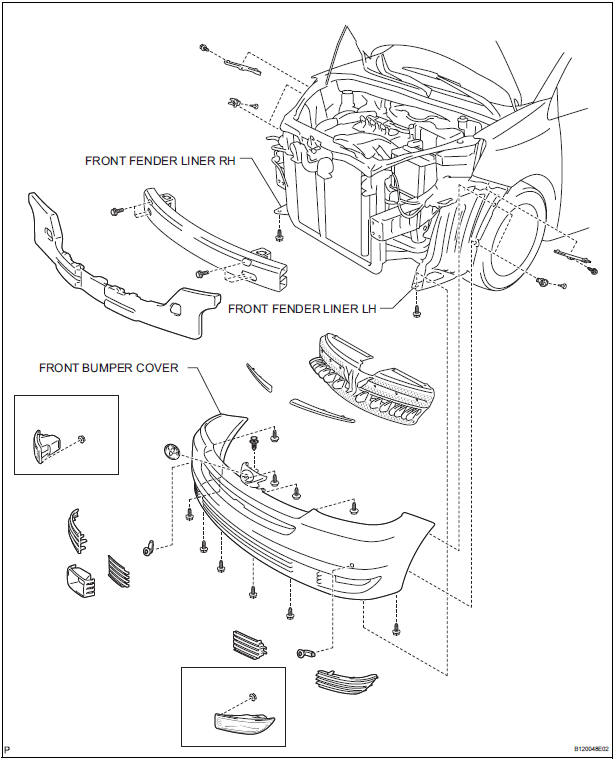
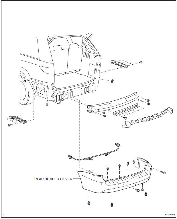
COMPONENTS

REMOVAL
1. REMOVE FRONT FENDER LINER LH
2. REMOVE FRONT FENDER LINER RH
3. REMOVE FRONT BUMPER COVER
4. REMOVE REAR BUMPER COVER (2)
5. REMOVE NO. 1 ULTRASONIC SENSOR RETAINER
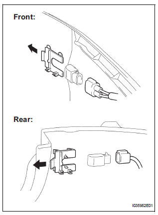
- Remove the No. 1 ultrasonic sensor retainer as shown in the illustration
6. REMOVE NO. 1 ULTRASONIC SENSOR
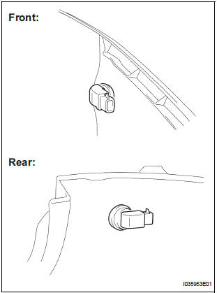
- Disconnect the connector and remove the No. 1 ultrasonic sensor.
INSPECTION
1. INSPECT NO.1 ULTRASONIC SENSOR
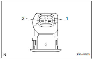
- Measure the resistance according to the value(s) in the table below.
Standard resistance
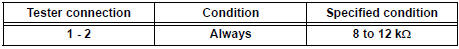
If the result is not as specified, replace No.1 ultrasonic sensor
INSTALLATION
1. INSTALL NO. 1 ULTRASONIC SENSOR
- Connect the connector and install the No. 1 ultrasonic sensor.
2. INSTALL NO. 1 ULTRASONIC SENSOR RETAINER
- Install the No. 1 ultrasonic sensor retainer.
3. INSTALL REAR BUMPER COVER (3)
4. INSTALL FRONT BUMPER COVER
5. INSTALL FRONT FENDER LINER LH
6. INSTALL FRONT FENDER LINER RH
 Clearance warning ECU
COMPONENTS
REMOVAL
1. REMOVE FRONT DOOR SCUFF PLATE LH
2. REMOVE COWL SIDE TRIM BOARD LH
3. REMOVE INSTRUMENT PANEL FINISH PANEL SUBASSEMBLY LOWER LH
4. REMOVE NO. 1 INSTRUMENT PANEL SAFETY PAD ...
 No. 2 Ultrasonic sensor
COMPONENTS
REMOVAL
1. REMOVE REAR BUMPER COVER (2)
2. REMOVE NO. 1 ULTRASONIC SENSOR RETAINER
Remove the No. 1 ultrasonic sensor retainer as
shown in the illustration
3. REMO ...
Other materials:
Passenger Side Buckle Switch Circuit Malfunction
DTC B1771 Passenger Side Buckle Switch Circuit Malfunction
DESCRIPTION
The passenger side buckle switch circuit consists of the occupant
classification ECU and the front seat
inner belt assembly RH.
DTC B1771 is recorded when a malfunction is detected in the passenger side
buckle switch ci ...
Pressure Control Solenoid "B" Electrical (Shift
Solenoid Valve SL2)
DESCRIPTION
Shifting from 1st to 5th is performed in combination with "ON" and "OFF"
operation of the shift solenoid
valves SL1, SL2, SL3, S4 and SR which are controlled by the ECM. If an open or
short circuit occurs in
either of the shift solenoid valves, the ECM cont ...
DVD Error/ Excess Current/ Tray Insertion / Ejection Error
DTC 44-44 DVD Error
DTC 44-48 Excess Current
DTC 44-50 Tray Insertion / Ejection Error
DESCRIPTION
DTC No.
DTC Detection Condition
Trouble Area
44-44
Operation error in the DVD mechanism
Television display assembly
44-48
Excess current is prese ...
