Toyota Sienna Service Manual: Display Signal Circuit between Radio and Navigation Assembly and Television Camera Assembly
DESCRIPTION
This is the display signal circuit of the television camera assembly.
WIRING DIAGRAM

INSPECTION PROCEDURE
1 CHECK HARNESS AND CONNECTOR (RADIO AND NAVIGATION ASSEMBLY - TELEVISION CAMERA ASSEMBLY)
- Disconnect the R10 connector from the radio and navigation assembly.
- Disconnect the T10 connector from the television camera assembly.
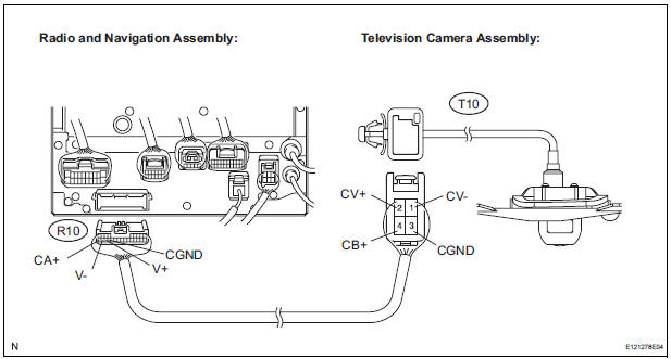
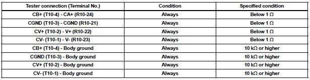
- Measure the resistance according to the value(s) in the table below.
Standard resistance
2 INSPECT RADIO AND NAVIGATION ASSEMBLY
- Reconnect the radio and navigation assembly R10 connector.
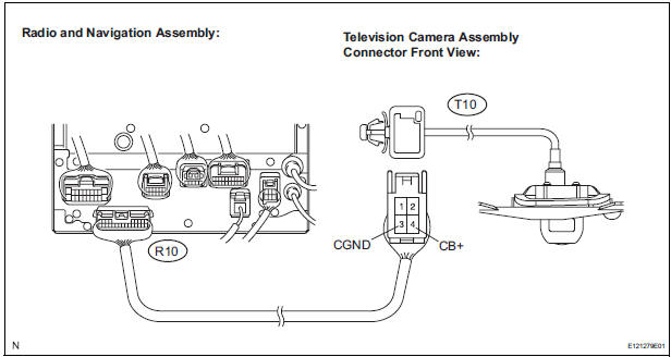
- Measure the voltage according to the value(s) in the table below
Standard voltage

3 INSPECT TELEVISION CAMERA ASSEMBLY
- Reconnect the radio and navigation assembly R10 connector and the television camera assembly T10 connector.
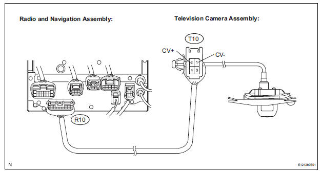
- Check the waveform of the television camera assembly using an oscilloscope.
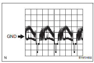
- Measurement terminal: CV+ - CVMeasurement setting: 0.2 V/DIV, 0.2 μs/DIV Condition: Ignition switch ON, Shift lever in R range
OK: Pulses as shown in the illustration.
PROCEED TO NEXT CIRCUIT INSPECTION SHOWN IN PROBLEM SYMPTOMS TABLE
 Reverse Signal Circuit
DESCRIPTION
The radio and navigation assembly receives a reverse signal from the
park/neutral position switch.
WIRING DIAGRAM
INSPECTION PROCEDURE
1 INSPECT RADIO AND NAVIGATION ASSEMBLY
...
 Clearance warning ECU
COMPONENTS
REMOVAL
1. REMOVE FRONT DOOR SCUFF PLATE LH
2. REMOVE COWL SIDE TRIM BOARD LH
3. REMOVE INSTRUMENT PANEL FINISH PANEL SUBASSEMBLY LOWER LH
4. REMOVE NO. 1 INSTRUMENT PANEL SAFETY PAD ...
Other materials:
Removal
1. REMOVE INSTRUMENT PANEL SUB-ASSEMBLY WITH PASSENGER AIRBAG ASSEMBLY
HINT:
Refer to the instructions for removal of the instrument
panel sub-assembly w/ passenger airbag assembly (See
page IP-5).
2. REMOVE HEATER TO FOOT DUCT NO.1
(a) Remove the clip and the heater to foot duct No. 1.
3 ...
Occupant Classification System Malfunction
DTC B1150/23 Occupant Classification System Malfunction
DESCRIPTION
The occupant classification system circuit consists of the center airbag
sensor assembly and the occupant
classification ECU.
If the center airbag sensor assembly receives signals from the occupant
classification ECU, it d ...
DTC check / clear
1. CHECK DTC (USING INTELLIGENT TESTER)
Checking DTCs.
Connect the intelligent tester to the DLC3.
Turn the ignition switch ON.
Read DTCs by following the prompts on the
tester screen.
HINT:
Refer to the intelligent tester operator's manual
for further deta ...
