Toyota Sienna Service Manual: Components
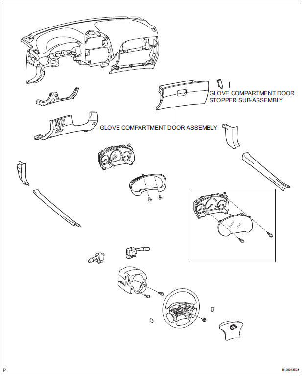

 Removal
1. REMOVE GLOVE COMPARTMENT DOOR STOPPER
SUB-ASSEMBLY
2. REMOVE GLOVE COMPARTMENT DOOR
ASSEMBLY
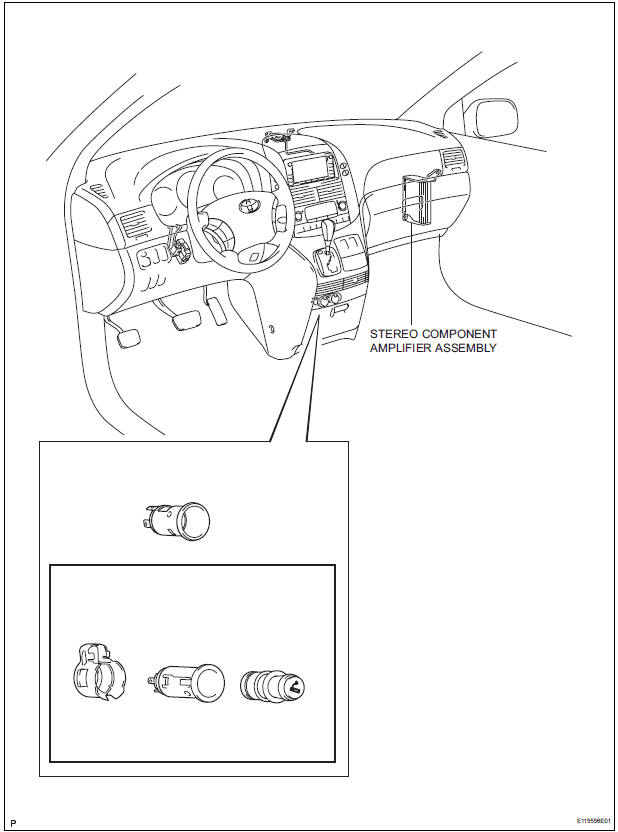
3. REMOVE STEREO COMPONENT AMPLIFIER
ASSEMBLY (W/ STEREO COMPONENT AMPLIFIER)
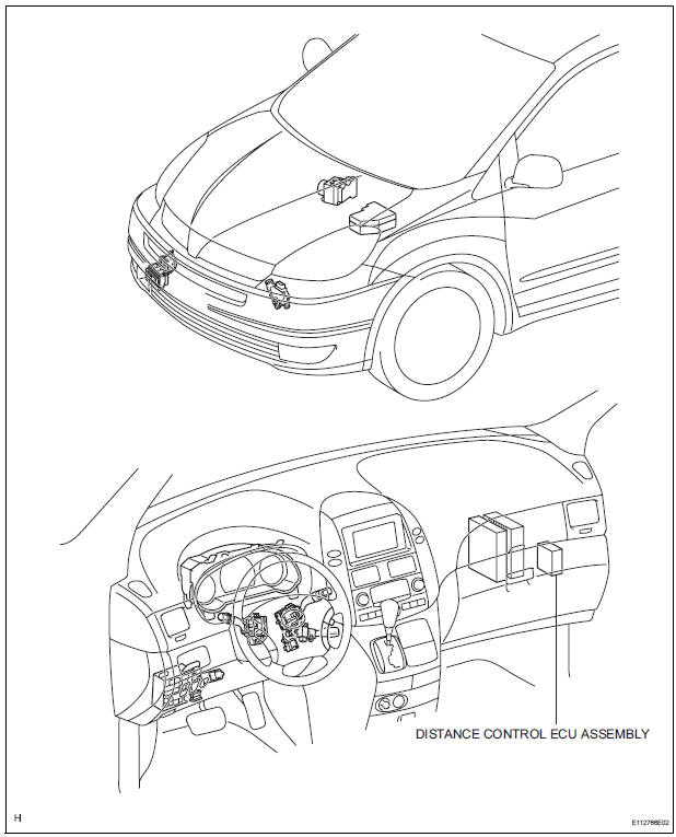
4. REMOVE DISTANCE C ...
Other materials:
Throttle / Pedal Position Sensor
HINT:
These DTCs relate to the Accelerator Pedal Position (APP) sensor.
DESCRIPTION
HINT:
This ETCS (Electronic Throttle Control System) does not use a throttle cable.
The Accelerator Pedal Position (APP) sensor is integrated with the accelerator
pedal bracket and has 2
sensor circuits ...
Disassembly
1. HOLD VANE PUMP ASSEMBLY
(a) Using SST, hold the vane pump assembly in a vise.
SST 09630-00014 (09631-00132)
2. REMOVE POWER STEERING SUCTION PORT UNION
(a) Remove the bolt and the power steering suction port
union from the vane pump front housing.
(b) Using a screwdriver, remove ...
Open in Driver Side Squib 2nd Step Circuit
DTC B1181/18 Open in Driver Side Squib 2nd Step Circuit
DESCRIPTION
The driver side squib 2nd step circuit consists of the center airbag sensor
assembly, the spiral cable and
the steering pad.
The circuit instructs the SRS to deploy when deployment conditions are met.
DTC B1181/18 is reco ...
