Toyota Sienna Service Manual: Compressor Solenoid Circuit
DESCRIPTION
In this circuit, the compressor receives a refrigerant compression demand signal from the A/C amplifier.
Based on this signal, the compressor changes the amount of compressor output.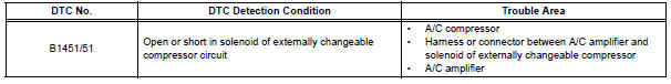
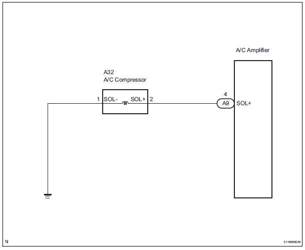
WIRING DIAGRAM
INSPECTION PROCEDURE
1 INSPECT A/C COMPRESSOR
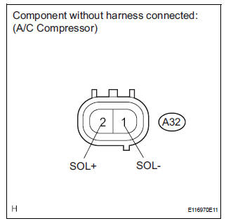
(a) Disconnect the A/C compressor connector.
(b) Measure the resistance according to the value(s) in the table below.
Standard resistance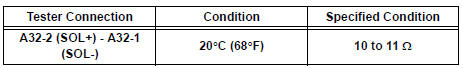


2 CHECK HARNESS AND CONNECTOR (A/C COMPRESSOR - BODY GROUND)
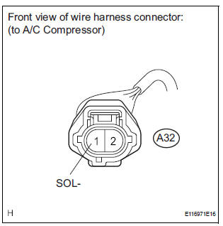
(a) Disconnect the A/C compressor connector.
(b) Measure the resistance according to the value(s) in the table below.
Standard resistance 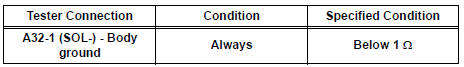

3 CHECK HARNESS AND CONNECTOR (A/C COMPRESSOR - A/C AMPLIFIER)
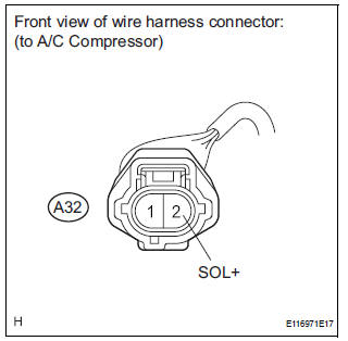
(a) Disconnect the A/C compressor connector.
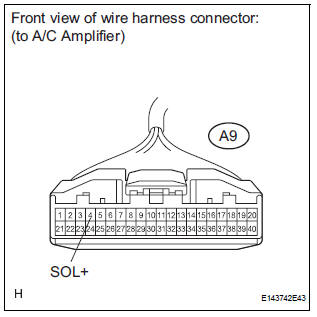
(b) Disconnect the A/C amplifier connector.
(c) Measure the resistance according to the value(s) in the table below
Standard resistance 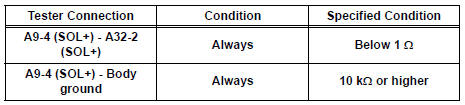
Result 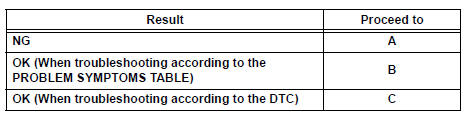

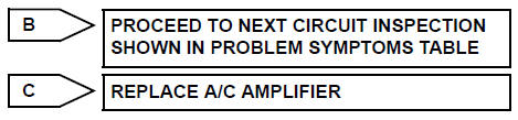
REPAIR OR REPLACE HARNESS OR CONNECTOR
 Rear Air Outlet Damper Control Servo Motor Circuit
DESCRIPTION
This circuit turns the servo motor and changes each damper position by
receiving the signals from the A/
C amplifier.
The rear air outlet damper servo motor switches the air outlet ...
 Multiplex Communication Circuit
DESCRIPTION
INSPECTION PROCEDURE
1 GO TO CAN COMMUNICATION SYSTEM
(a) Refer to the CAN communication system (See page CA-
7).
(b) If the CAN communication system is operating normally,
procee ...
Other materials:
Starting the engine
Shift the shift lever to P and apply the brakes.
Touch the Toyota emblem side
of the electronic key to the
engine switch.
An alarm will sound to indicate that
the start function cannot detect the
electronic key that is touched to the
engine switch if any of the doors is
opened ...
Transmission Range Sensor Circuit Malfunction
(PRNDL Input)
DESCRIPTION
The park/neutral position switch detects the shift lever position and sends
signals to the ECM.
MONITOR DESCRIPTION
These DTCs indicate a problem with the park/neutral position switch and the
wire harness in the park/
neutral position switch circuit.
The park/neutral po ...
Inspection
1. INSPECT OIL PUMP ASSEMBLY
(a) Turn the drive gear with the 2 screwdrivers and
make sure that it rotates smoothly.
NOTICE:
Be careful not to damage the oil seal lip.
2. INSPECT CLEARANCE OF OIL PUMP ASSEMBLY
(a) Push the driven gear to one side of the body.
(b) Using ...
