Toyota Sienna Service Manual: Actuator check
1. ACTUATOR CHECK
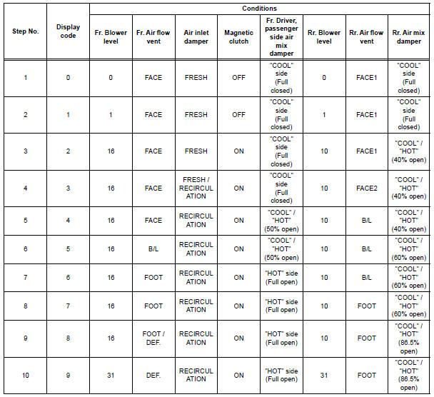
(a) After entering the DTC check mode (Sensor Check Mode), press the R/F switch.
(b) As each damper, motor and relay automatically operate actuator check at 1-second intervals from step No. 1 to No. 10 continuously, check the temperature and air flow visually and by hand.
If the slower display is desired, press the DEF switch and change it to step operation. Each time the DEF switch is pressed, the display changes by 1 step.
HINT:
- Codes are displayed from smaller to larger numbers in order.
- To cancel the check mode, press the OFF switch.
- Room Temperature Sensor Circuit
- Ambient temperature sensor circuit
- Evaporator temperature sensor circuit
- Rear evaporator temperature sensor circuit
- Rear Room Temperature Sensor Circuit
- Solar Sensor Circuit (Passenger Side)
- Compressor Lock Sensor Circuit
- Pressure Sensor Circuit
- Solar Sensor Circuit (Driver Side)
- Air Mix Damper Position Sensor Circuit (Passenger Side)
- Air Inlet Damper Position Sensor Circuit
- Air Outlet Damper Position Sensor Circuit
- Air Mix Damper Position Sensor Circuit (Driver Side)
- Rear Air Mix Damper Position Sensor Circuit
- Rear Air Outlet Damper Position Sensor Circuit
- Air Mix Damper Control Servo Motor Circuit (Passenger Side)
- Air Inlet Damper Control Servo Motor Circuit
- Air Outlet Damper Control Servo Motor Circuit
- Air Mix Damper Control Servo Motor Circuit (Driver Side)
- Rear Air Mix Damper Control Servo Motor Circuit
- Rear Air Outlet Damper Control Servo Motor Circuit
- Compressor Solenoid Circuit
- Multiplex Communication Circuit
- Blower Motor Circuit
- Air Conditioning Compressor Magnetic Clutch Circuit
- Rear Air Conditioning Control Panel Circuit
- Rear Air Conditioning Relay Circuit
- Rear Blower Motor Circuit
- IG Power Source Circuit
- ACC Power Source Circuit
- Back-up Power Source Circuit
 Diagnostic trouble code chart
If a trouble code is displayed during the DTCs check (sensor
check), check the circuit listed for the code in the table below
(Proceed to the page given for that circuit).
AIR CONDITIONING SYSTEM
...
 Room Temperature Sensor Circuit
DESCRIPTION
This sensor detects the cabin temperature that is used as the basis for
temperature control and sends a
signal to the A/C amplifier.
WIRING DIAGRAM
INSPECTION PROCEDURE
1 READ VAL ...
Other materials:
Power Back Door Warning Buzzer does not Sound
DESCRIPTION
The power back door system uses a warning buzzer built into the
back door, which has 3 ways of
sounding that are used differently according to the situations:
When all the following conditions are met, the warning buzzer sounds at
a cycle of 0.3 seconds:
* The ignitio ...
Reassembly
1. INSTALL REAR DRIVE SHAFT OUTBOARD JOINT BOOT
HINT:
Before install the boot, wrap the spline of the outboard
joint shaft with vinyl tape to prevent the boot from
bearing damaged.
(a) Install new outboard joint boot, 2 outboard joint boot
clamps, 2 inboard joint boot clamps and inboard
j ...
Removal
1. REMOVE BATTERY
2. REMOVE AIR CLEANER ASSEMBLY
HINT:
(See page EM-26)
3. REMOVE SPEED SENSOR (NT SENSOR)
(a) Disconnect the speed sensor connector.
(b) Remove the bolt and speed sensor.
4. REMOVE SPEED SENSOR (NC SENSOR)
(a) Disconnect the speed sensor connector.
(b) Remove th ...
