Toyota Sienna Service Manual: Control Module Performance
DTC P0607 Control Module Performance
DESCRIPTION
The ECM continuously monitors its main and sub CPUs. This self-check ensures that the ECM is functioning properly. If outputs from the CPUs are different and deviate from the standards, the ECM will illuminate the MIL and set a DTC immediately.
The ECM also monitors the cruise control cancel circuit. If this circuit malfunctions, the ECM will set a DTC immediately (MIL is not illuminated).

NOTICE: First check for an exhaust gas leak around the HO2S if P0606 is present. An exhaust gas leak generates noise in the HO2S output. The ECM may interpret this as an HO2S transistor malfunction.
MONITOR STRATEGY
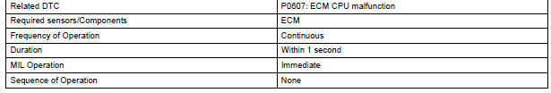
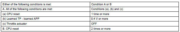
TYPICAL ENABLING CONDITIONS

TYPICAL MALFUNCTION THRESHOLDS
INSPECTION PROCEDURE
1 CHECK WHETHER DTC OUTPUT RECURS (IN ADDITION TO DTC P0607)
- Connect the intelligent tester to the DLC3.
- Turn the ignition switch to the ON position.
- Turn the tester on.
- Clear the DTC.
- Turn the ignition switch off.
- Disconnect the battery negative terminal and wait for 1 minute.
- Connect the battery negative terminal.
- Turn the ignition switch to the ON position.
- Enter the following menus: DIAGNOSIS / ENHANCED II / DTC INFO / CURRENT CODES.
- Read the DTCs.
Result
REPLACE ECM
 ECM / PCM Processor
DTC P0606 ECM / PCM Processor
DESCRIPTION
The ECM continuously monitors its internal processors (CPUs), A/F sensor
transistors and heated oxygen
sensor (HO2S) transistors. This self-check ensures ...
 Starter Relay Circuit High
DTC P0617 Starter Relay Circuit High
MONITOR DESCRIPTION
While the engine is being cranked, the positive battery voltage is applied to
terminal STA of the ECM.
If the ECM detects the Starter Co ...
Other materials:
Short to B+ in Rear Curtain Shield Squib LH
Circuit
DTC B1638/86 Short to B+ in Rear Curtain Shield Squib LH
Circuit
DESCRIPTION
The rear curtain shield squib LH circuit consists of the center airbag sensor
assembly and the curtain
shield airbag assembly LH.
The circuit instructs the SRS to deploy when deployment conditions are met.
DTC B ...
SFR Solenoid Circuit
DESCRIPTION
The solenoid comes on when signals are received from the ECU and controls the
pressure acting on the
wheel cylinders, thus controlling brake force.
WIRING DIAGRAM
INSPECTION PROCEDURE
1 RECONFIRM DTC
HINT:
These codes are detected when a problem is identified in the
...
Removal
1. DISCHARGE FUEL SYSTEM PRESSURE
HINT:
See page FU-1.
2. DISCONNECT CABLE FROM NEGATIVE BATTERY
TERMINAL
3. REMOVE NO. 1 ENGINE UNDER COVER
4. DRAIN ENGINE COOLANT (See page CO-6)
5. REMOVE FRONT WIPER ARM HEAD CAP (See page
WW-4)
6. REMOVE FRONT WIPER ARM RH (See page WW-4)
7. REMOVE FRO ...
