Toyota Sienna Service Manual: Data list / active test
1. DATA LIST
HINT: By the DATA LIST displayed by the intelligent tester, you can read the value of the switch, sensor, actuator and so on without removing any part. Reading the DATA LIST as the first step in troubleshooting is one of the methods to shorten the labor time.
- Connect the intelligent tester to DLC3.
- Turn the ignition switch ON.
- According to the display on the tester, read the "DATA LIST".
BODY NO.1:
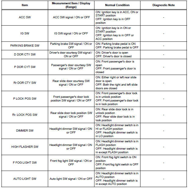
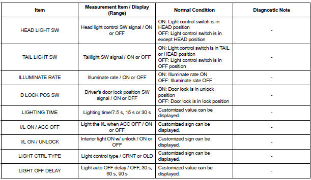
BACK DOOR:

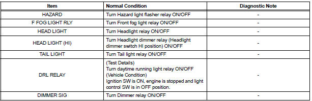
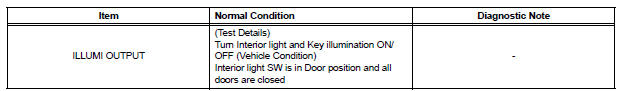
2. ACTIVE TEST
HINT: Performing the ACTIVE TEST using the intelligent tester allows the relay, VSV, actuator and so on to operate without removing any part. Performing the ACTIVE TEST as the first step of troubleshooting is one of the methods to shorten the labor time. The DATA LIST can be displayed during the ACTIVE TEST.
- Connect the intelligent tester to DLC3.
- Turn the ignition switch ON.
- According to the display on the tester, perform the "ACTIVE TEST".
BODY NO.1:
 DTC check / clear
1. USING INTELLIGENT TESTER
Hook up the intelligent tester to the DLC3.
Monitor the ECU data by following the prompts on
the tester screen.
HINT:
intelligent tester has "S ...
 Diagnostic trouble code chart
1. DTC CHECK
If a malfunction code is displayed during the DTC check ,
check the suspected area listed for that code in the table
below, and proceed to the appropriate page.
DIAGNOSTIC TROUBLE COD ...
Other materials:
DVD-ROM Abnormal
DVD-ROM Abnormal
DESCRIPTION
DTC No.
DTC Detection Condition
Trouble Area
44-43
DVD-ROM operation is abnormal.
DVD
Television display assembly
INSPECTION PROCEDURE
HINT:
After the inspection is completed, clear the DTCs ...
Editing the contact data
For PBAP compatible Bluetooth® phones, this function is available when
“Automatic Transfer” is set to off.
Select “Edit Contact”.
Select the desired contact.
Select corresponding to the
desired name or number.
For editing the name
Follow the steps in “Registerin ...
Back Sonar Sensor LH Circuit
DESCRIPTION
An ultrasonic sensor consists of a sensor portion that transmits and receives
ultrasonic waves and a preamplifier
that amplifies them. The ultrasonic sensor outputs the ultrasonic waves and
sends the received
signals to the clearance warning ECU.
WIRING DIAGRAM
INSPECTION PR ...
