Toyota Sienna Service Manual: Entire Combination Meter does not Operate
DESCRIPTION
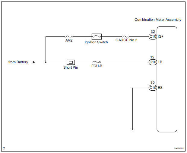
This is the power source circuit to operate the combination meter assembly.
WIRING DIAGRAM
INSPECTION PROCEDURE
1 INSPECT COMBINATION METER ASSEMBLY
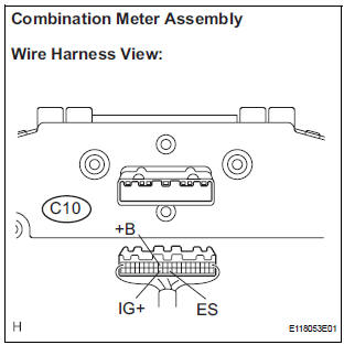
- Disconnect the C10 connector.
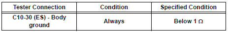
- Measure the resistance according to the value(s) in the table below.
Standard resistance
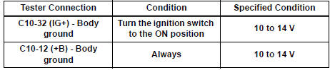
- Measure the voltage according to the value(s) in the table below.
Standard voltage
REPLACE COMBINATION METER ASSEMBLY
 On-vehicle inspection
1. INSPECT SPEEDOMETER
Check the operation.
Using a speedometer tester, check the
speedometer indication according to the table
below.
Reference: mph (U.S.A.)
Referen ...
 Speedometer Malfunction
DESCRIPTION
Factors that affect the indicated vehicle speed include tire size, tire
inflation, and tire wear. The speed indicated on the speedometer has an
allowable margin of error. This can be ...
Other materials:
Charge Warning Light Comes ON while Driving
INSPECTION PROCEDURE
1 CHECK LOCK FUNCTION OF CLUTCH PULLEY
(a) Check the lock function with the pulley installed in the
vehicle.
(1) Visually check that the rotor in the generator
operates with the engine started.
(b) Check the lock function with the pulley removed from the
vehicle.
( ...
Diagnostic trouble code chart
HINT:
The parameters listed in the chart may not confirm exactly to
those read during the DTC check due to the type of
instrument or other factors.
If a trouble code is displayed during the DTC check in the
check mode, check the circuit for the code listed in the table
below. For details of ...
How to proceed with
troubleshooting
The intelligent tester can be used in steps 4, 6, 8 and 9.
1 VEHICLE BROUGHT TO WORKSHOP
2 CUSTOMER PROBLEM ANALYSIS
3 PASSENGER AIRBAG ON/OFF INDICATOR CHECK
4 DTCs CHECK (Present and Past DTCs)
Check for DTCs.
Result
5 DTCs CHART
6 CIRCUIT INSPECTION
7 REPAIR
8 CLEAR DTCs (Present ...
