Toyota Sienna Service Manual: Data list / active test
1. DATA LIST
HINT: Using the DATA LIST displayed on the intelligent tester, you can read the value of the switch, sensor, actuator, etc. without parts removal. Reading the DATA LIST as the first step of troubleshooting is one way to shorten the labor time.
- Connect the intelligent tester to the DLC3.
- Turn the ignition switch ON.
- Read the DATA LIST according to the display on the tester.
Power slide door ECU LH/RH:
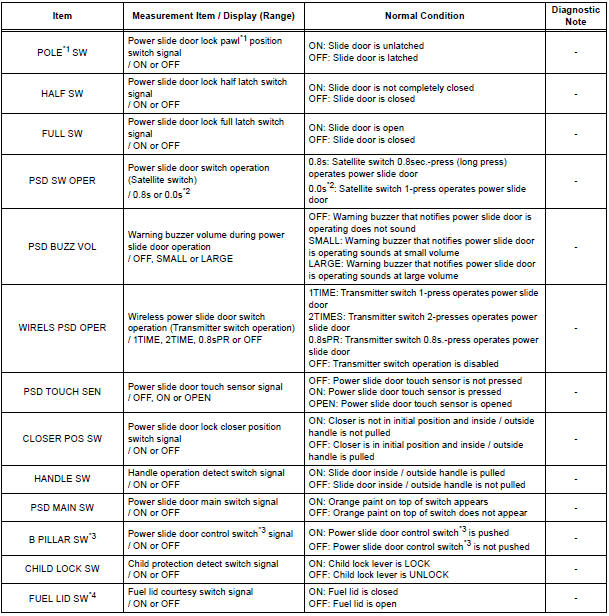
*1 "POLE" appears on the display of the intelligent tester, however the name of the part corresponding to the display of the tester is "pawl".
*2 "0.0s" appearing on the display of the intelligent tester means that a 1-press of the satellite switch operates the power slide door.
*3 "B PILLAR SW" appears on the display of the intelligent tester, however the name of the part corresponding to the display of the tester is "Power slide door control switch".
*4 Power slide door ECU LH only.
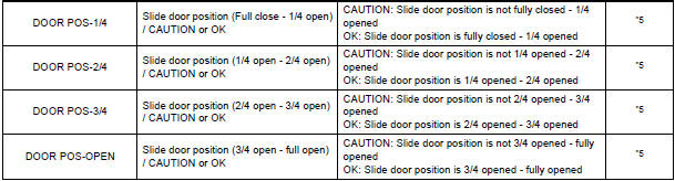
*5 In case that the "CAUTION" is displayed even without resistance applied in each range, there must be a foreign object caught somewhere in that range.
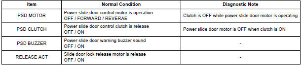
2. ACTIVE TEST
HINT: Performing the ACTIVE TEST using the intelligent tester allows you to operate the relay, VSV, actuator, etc.
without parts removal. Performing the ACTIVE TEST as the first step of troubleshooting is one way to shorten the labor time. It is possible to display the DATA LIST during the ACTIVE TEST.
- Connect the intelligent tester to the DLC3.
- Turn the ignition switch ON.
- Perform the ACTIVE TEST according to the display on the tester.
Power Slide Door ECU LH/RH
 DTC check / clear
1. CHECK DTC (USING INTELLIGENT TESTER)
Checking DTCs.
Connect the intelligent tester to the DLC3.
Turn the ignition switch ON.
Read DTCs by following the prompts o ...
 Diagnostic trouble code chart
If a malfunction code is displayed during the DTC check,
check the circuit listed for that code in the table below.
(Proceed to the page given for that circuit.)
POWER SLIDE DOOR SYSTEM
...
Other materials:
Heated steering
wheel/seat heaters
Heated steering wheel and seat heaters heat the side grips of the
steering wheel and seats, respectively.
WARNING
Care should be taken to prevent injury if anyone in the
following categories
comes in contact with the steering wheel and seats when the heater
is on:
...
Installation
1. INSTALL STEERING ANGLE SENSOR
(a) Install the steering sensor onto the spiral cable.
2. PLACE FRONT WHEELS FACING STRAIGHT AHEAD
3. INSTALL SPIRAL CABLE SUB-ASSEMBLY (See page
RS-434)
4. INSTALL STEERING COLUMN COVER LWR (See
page RS-435)
5. CENTER SPIRAL CABLE (See page RS-435)
6. IN ...
Check for intermittent
problems
1. CHECK FOR INTERMITTENT PROBLEMS
HINT:
For use of the intelligent tester only:
Inspect the vehicle's ECM using check mode.
Intermittent problems are easier to detect with an
intelligent tester when the ECM is in check mode. In
check mode, the ECM uses 1 trip detection logic, which
is more ...
