Toyota Sienna Service Manual: On-vehicle inspection
1. INSPECT DRIVE BELT
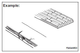
(a) Visually check the drive belt for excessive wear, frayed cords, etc.
If any defect is found, replace the drive belt.
HINT: Cracks on the rib side of a belt are considered acceptable. Replace the belt if there are any missing ribs.
2. CHECK POWER STEERING FLUID LEVEL
(a) Keep the vehicle level.
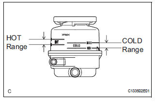
(b) With the engine stopped, check the fluid level in the fluid reservoir.
If necessary, add fluid.
Fluid: ATF DEXRON II or III, or equivalent
HINT: If the fluid is hot, check that the fluid level is within the HOT range on the fluid reservoir. If the fluid is cold, check that the fluid level is within the COLD range.
(c) Start the engine and run it at idle.
(d) Turn the steering wheel from lock to lock several times to raise fluid temperature.
Fluid temperature: 75 to 80°C (167 to 176°F)
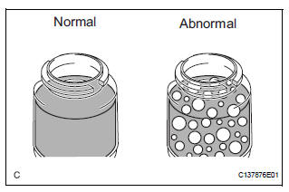
(e) Check for foaming or emulsification.
If foaming or emulsification is identified, bleed the power steering system (See page PS-6).
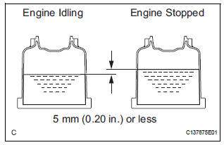
(f) With the engine idling, measure the fluid level in the fluid reservoir.
(g) Stop the engine.
(h) Wait a few minutes and remeasure the fluid level in the fluid reservoir.
Maximum fluid level rise: 5 mm (0.20 in.)
If a problem is found, bleed the power steering system (See page PS-6).
(i) Check the fluid level.
3. INSPECT STEERING FLUID PRESSURE
(a) Disconnect the pressure feed tube assembly from the vane pump assembly (See page PS-9).
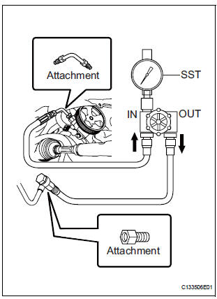
(b) Connect SST as shown in the illustration.
SST 09640-10010 (09641-01010, 09641-01060, 09641-01030)
NOTICE: Check that the valve of SST is in the open position.
(c) Bleed the power steering system (See page PS-6).
(d) Start the engine and run it at idle.
(e) Turn the steering wheel from lock to lock several times to raise fluid temperature.
Fluid temperature: 75 to 80°C (167 to 176°F)
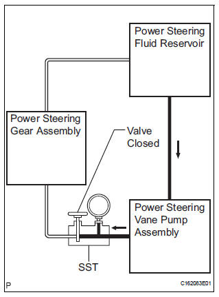
(f) With the engine idling, close the valve of SST and observe the reading on SST.
Standard fluid pressure: 7,800 to 8,300 kPa (79.5 to 84.6 kgf/cm2, 1,131 to 1,204 psi)
NOTICE:
- Do not keep the valve closed for more than 10 seconds.
- Do not allow the fluid temperature to become too high.
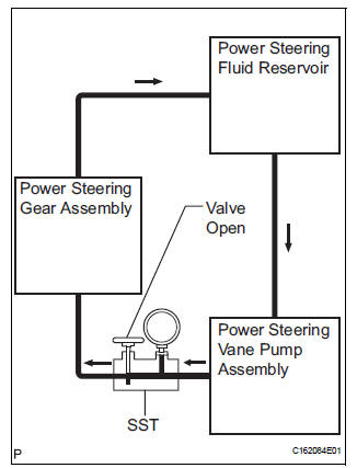
(g) With the engine idling, open the valve fully.
(h) Measure the fluid pressure at engine speeds of 1,000 rpm and 3,000 rpm.
Fluid pressure difference: 490 kPa (5 kgf/cm2, 71 psi) or less
NOTICE: Do not turn the steering wheel.
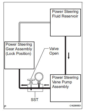
(i) With the engine idling and the valve fully opened, turn the steering wheel left or right to the full lock position. Observe the reading on SST.
Standard fluid pressure: 7,800 to 8,300 kPa (79.5 to 84.6 kgf/cm2, 1,131 to 1,204 psi)
NOTICE:
- Do not keep the steering wheel in the full lock position for more than 10 seconds.
- Do not allow the fluid temperature to become too high.
(j) Disconnect SST.
(k) Connect the pressure feed tube assembly to the vane pump assembly (See page PS-19).
(l) Bleed the power steering system (See page PS-6).
4. CHECK STEERING EFFORT
(a) Stop the vehicle on a level, paved surface and turn the wheels straight ahead.
(b) Disconnect the negative (-) battery cable from the battery.
| CAUTION: Wait at least 90 seconds after disconnecting the cable from the negative (-) battery terminal to prevent airbag and seat belt pretensioner activation. |
(c) Remove the steering pad (See page RS-423).
(d) Connect the negative (-) battery cable to the battery.
(e) Using a torque wrench, check if the steering wheel set nut is properly tightened.
Torque: 50 N*m (510 kgf*cm, 37 ft.*lbf)
(f) Start the engine and run it at idle.
(g) Turn the steering wheel 90 degrees to the right and check steering effort (torque) while turning the wheel. Check the opposite direction in the same manner.
Torque: Steering effort (Reference) 6.0 N*m (61 kgf*cm, 53 in.*lbf)
HINT: Check the tire type, pressure, and the road surface before making your diagnosis.
h) Disconnect the negative (-) battery cable from the battery.
(i) Tighten the steering wheel set nut.
Torque: 50 N*m (510 kgf*cm, 37 ft.*lbf)
(j) Install the steering pad (See page RS-424).
(k) Connect the negative (-) battery cable to the battery.
(l) Clear the DTCs (See page RS-35).
(m) Inspect the airbag warning light (See page RS-27).
 Problem symptoms table
HINT:
Use the table below to help determine the cause of the
problem. Likely causes of the problem are indicated in
descending order. Check each suspected area in order.
Repair or replace the fa ...
 Power steering fluid
Bleeding
1. BLEED POWER STEERING SYSTEM
(a) Check the fluid level (See page PS-2).
(b) Jack up the front of the vehicle and support it with
stands.
(c) Turn the steering wheel.
(1) With th ...
Other materials:
Jam Protection Function Activates During Power Slide Door RH
Operation
DESCRIPTION
It may be caused by ill-fitting slide door, faulty touch sensor or
faulty pulse sensor.
The power slide door ECU activates the slide motor to open / close
the power slide door, thus
controlling the power slide door operation. For jam and foreign object
detect ...
Front Occupant Classification Sensor LH Collision
Detection
DTC B1785 Front Occupant Classification Sensor LH Collision
Detection
DESCRIPTION
DTC B1785 is output when the occupant classification ECU receives a collision
detection signal sent by
the front occupant classification sensor LH if an accident occurs.
DTC B1785 is also output when the front ...
Air Inlet Damper Control Servo Motor Circuit
DESCRIPTION
The air inlet control servo motor is controlled by the A/C amplifier and
moved to the desired position.
The air inlet control servo motor switches the air inlet mode by rotating
(normal, reverse) with electrical
power from the A/C amplifier. This controls intake air and changes ...
