Toyota Sienna Service Manual: Sound Signal Circuit between Radio and Navigation Assembly and Television Display Assembly
DESCRIPTION
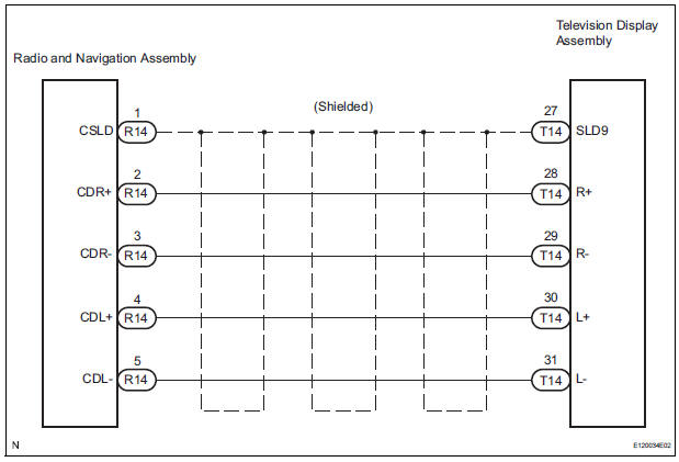
The television display assembly sends an RSE sound signal to the radio and navigation assembly through this circuit. The sound signal that has been sent is amplified by the stereo component amplifier, and then is sent to the speakers.
If there is an open or short in the circuit, sound cannot be heard from the speakers even if there is no malfunction in the stereo component amplifier, radio and navigation assembly or speakers.
WIRING DIAGRAM
INSPECTION PROCEDURE
1 CHECK HARNESS AND CONNECTOR (RADIO AND NAVIGATION ASSEMBLY - TELEVISION DISPLAY ASSEMBLY)
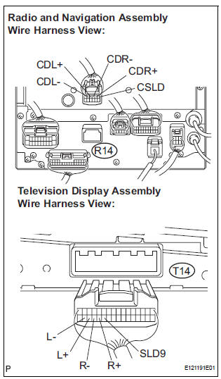
- Disconnect the connectors from the television display assembly and radio and navigation assembly.
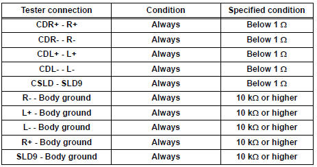
- Measure the resistance according to the value(s) in the table below.
Standard resistance
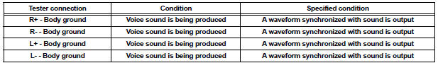
2 INSPECT TELEVISION DISPLAY ASSEMBLY
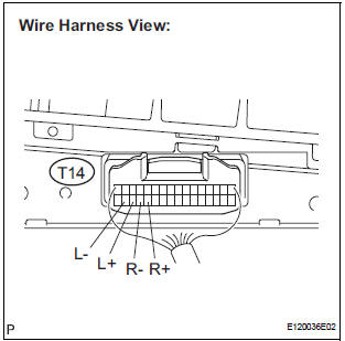
- Reconnect the television display assembly connector and radio and navigation assembly connectors.
- Check the waveform according to the conditions in the table below
Standard resistance
PROCEED TO NEXT CIRCUIT INSPECTION SHOWN IN PROBLEM SYMPTOMS TABLE
 Speaker Circuit
DESCRIPTION
The sound signal that has been amplified by the stereo component amplifier is
sent to the speakers from
the stereo component amplifier through this circuit.
If there is a short in t ...
 Sound Signal Circuit between Radio and Navigation Assembly and
Stereo Component Amplifier
Sound Signal Circuit between Radio and Navigation Assembly and
Stereo Component Amplifier
DESCRIPTION
The radio and navigation assembly sends a sound signal to the stereo
component amplifier through this
circuit.
The sound signal that has been sent is amplified by the stereo compone ...
Other materials:
Adjustment procedure
Hold the steering wheel and
push the lever down.
Adjust to the ideal position by
moving the steering wheel horizontally
and vertically.
After adjustment, pull the lever up
to secure the steering wheel.
...
Open in Stop Light Switch Circuit
DTC C1249/49 Open in Stop Light Switch Circuit
DESCRIPTION
WIRING DIAGRAM
INSPECTION PROCEDURE
1 CHECK STOP LIGHT SWITCH OPERATION
(a) Check that the stop light comes on when the brake pedal
is depressed and goes off when the brake pedal is
released.
OK
HINT:
Check the stop li ...
Inspection procedure
1 BASIC INSPECTION
Check the conditions necessary for the power slide door
to open:
Power slide door main switch is in the ON position
(switch free: orange paint on the top of the switch
appears).
Slide door is unlocked (door lock position switch is
in the ON position when ...
