
Toyota Sienna 2010-2026 Owners Manual: Detection range of the sensors
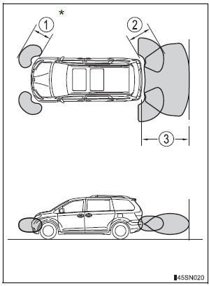
- Approximately 2.0 ft. (60 cm)
- Approximately 2.8 ft. (85 cm)
- Approximately 5.9 ft. (180 cm)
The diagram shows the detection range of the sensors. Note that the sensors cannot detect obstacles that are extremely close to the vehicle.
The range of the sensors may change depending on the shape of the object etc.
*: if equipped
 Sensor detection display, obstacle distance
Distance display
Sensors that detect an obstacle will illuminate continuously or blink.
*1: The images may differ from that shown in the illustrations.
*2: Multi-information display
*3: Audio ...
 Setting up intuitive parking assist
You can change the buzzer sound volume and the screen operating
conditions.
Press the “APPS� button.
Select “Setup� on the screen.
Select “Vehicle� on the screen.
Select “TOYO ...
Other materials:
Front No. 1 speaker
COMPONENTS
ON-VEHICLE INSPECTION
1. INSPECT FRONT NO.1 SPEAKER
HINT:
Remove interior parts so that the front No.1 speaker can
be seen.
Check the speaker installation.
OK:
The speaker is securely installed.
If the result is not as specified, reinstall the front
No.1 spe ...
Removal
1. REMOVE V-BANK COVER SUB-ASSEMBLY (See
page EM-28)
2. REMOVE NO. 1 ENGINE UNDER COVER (See page
EM-26)
3. DRAIN ENGINE COOLANT (See page CO-6)
4. REMOVE NO. 2 AIR CLEANER INLET (See page EM-
28)
5. REMOVE BATTERY (See page EM-26)
6. REMOVE FRONT BUMPER ASSEMBLY (See page
ET-3)
7. REMOVE ...
Checking tires
Check if the treadwear indicators are showing on the tires. Also check
the tires for uneven wear, such as excessive wear on one side of the
tread. Check the spare tire condition and pressure if not rotated.
New tread
Worn tread
Treadwear indicator
The location of treadwear indicator ...
