Toyota Sienna Service Manual: Diagnosis Circuit
DESCRIPTION
DTC output mode is set by connecting terminals TC and CG of the DLC3.
DTCs are displayed by blinking the SRS warning light.
HINT:
- When each warning light stays blinking, a ground short in the wiring of terminal TC of the DLC3 or an internal ground short in each ECU is suspected.
- A DTC output mode signal is transmitted through BEAN and CAN to each ECU including the center airbag sensor assembly. Thus when all systems do not enter DTC output mode, there may be an ECM malfunction
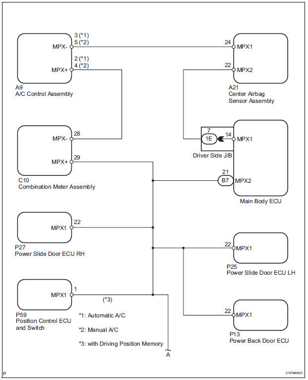
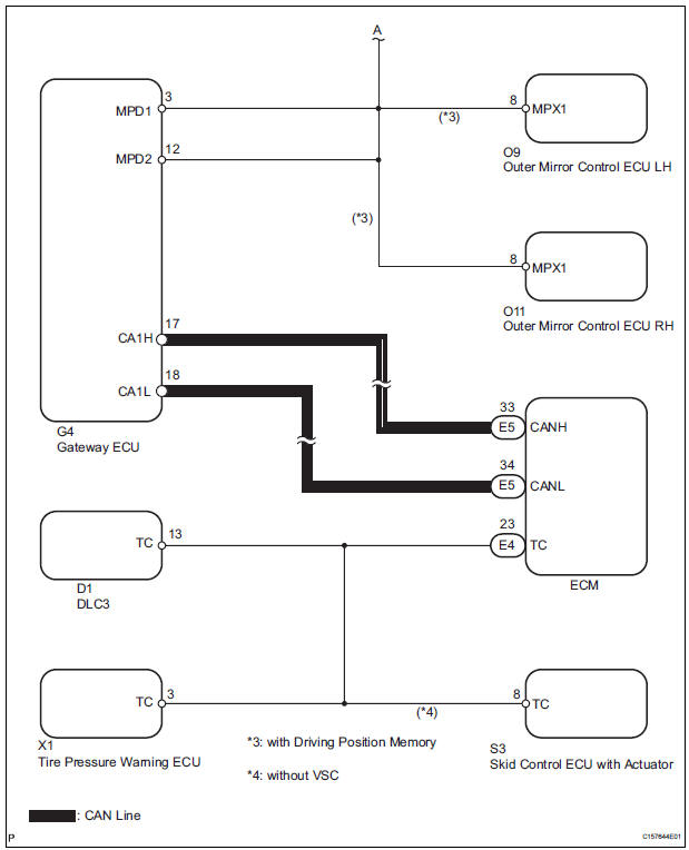
WIRING DIAGRAM
INSPECTION PROCEDURE
1 CHECK MULTIPLEX COMMUNICATION SYSTEM
- Check if the multiplex communication system DTC is output.
HINT: The center airbag sensor assembly of this system is connected to the multiplex communication system.
Therefore, before starting troubleshooting, make sure to check that there is no trouble in the multiplex communication system.
OK: The Multiplex communication system DTC is not output.
 REPAIR CIRCUITS INDICATED BY
OUTPUT
DTCS
REPAIR CIRCUITS INDICATED BY
OUTPUT
DTCS

2 CHECK CAN COMMUNICATION SYSTEM
- Use the intelligent tester to check if the CAN communication system is functioning normally.
HINT: The ECM is connected to the CAN communication system. Therefore, before starting troubleshooting, make sure to check that there is no trouble in the CAN communication system.
OK: The CAN communication system is functioning normally.
 REPAIR CAN COMMUNICATION
CIRCUIT
REPAIR CAN COMMUNICATION
CIRCUIT

3 CHECK WIRE HARNESS (TC OF DLC3 - TC OF ECM)
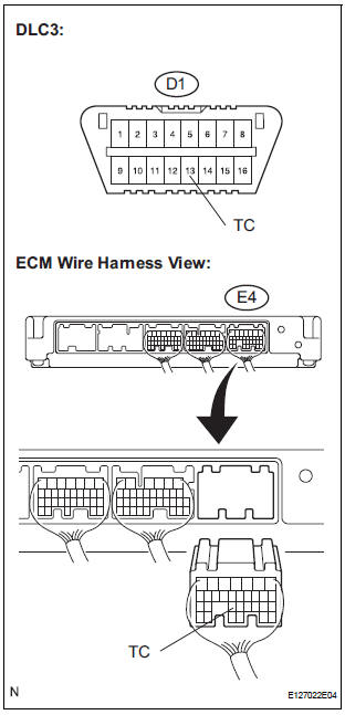
- Turn the ignition switch to the LOCK position.
- Disconnect the connector from the ECM.
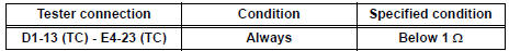
- Measure the resistance according to the value(s) in the table below.
Standard resistance
 REPAIR OR REPLACE WIRE
HARNESS (TC
OF DLC3 - TC OF ECM)
REPAIR OR REPLACE WIRE
HARNESS (TC
OF DLC3 - TC OF ECM)

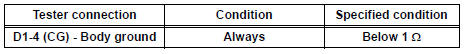
4 CHECK WIRE HARNESS (CG OF DLC3 - BODY GROUND)
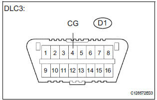
- Measure the resistance according to the value(s) in the table below.
Standard resistance
 REPAIR OR REPLACE WIRE
HARNESS (CG
OF DLC3 - BODY GROUND)
REPAIR OR REPLACE WIRE
HARNESS (CG
OF DLC3 - BODY GROUND)

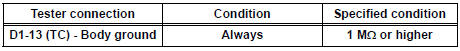
5 CHECK WIRE HARNESS (TC OF DLC3 - BODY GROUND)
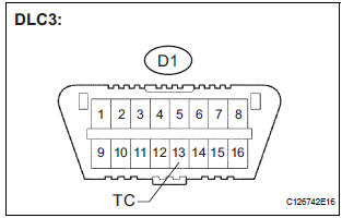
- Measure the resistance according to the value(s) in the table below.
Standard resistance
 REPAIR OR REPLACE WIRE
HARNESS OR
EACH ECU
REPAIR OR REPLACE WIRE
HARNESS OR
EACH ECU

REPLACE CENTER AIRBAG SENSOR ASSEMBLY
 SRS Warning Light does not Come ON
DESCRIPTION
WIRING DIAGRAM
INSPECTION PROCEDURE
1 CHECK BATTERY
Measure the voltage of the battery.
Standard voltage:
11 to 14 V
CHECK AND REPLACE BATTERY OR
CHARGING SYSTEM
2 CHECK CO ...

Other materials:
Components
REMOVAL
1. DISCONNECT CABLE FROM NEGATIVE BATTERY
TERMINAL
2. REMOVE FRONT BUMPER ASSEMBLY
3. REMOVE FOG LIGHT ASSEMBLY
Disengage the 2 claws
Disengage the 2 pins and remove the fog light
assembly.
DISASSEMBLY
1. REMOVE FOG LIGHT BULB
Turn in the dir ...
Air Intake Control Circuit
DESCRIPTION
The air cleaner is equipped with two inlets, one of which is opened or closed
by the Air Intake Control
Valve (AICV). This system reduces intake noise and increases engine power at
low-to-high engine speed
range.
When the engine is operating in the low-to-mid speed range, this ...
Vehicle Speed Signal Circuit between Radio and Navigation Assembly
and Combination Meter
DESCRIPTION
The radio and navigation assembly receives a vehicle speed signal from the
combination meter and
information about the GPS antenna, and then adjusts vehicle position.
HINT:
A voltage of 12 V or 5 V is output from each ECU and then input to
the combination meter. The sig ...
