Toyota Sienna Service Manual: SRS Warning Light does not Come ON
DESCRIPTION
WIRING DIAGRAM
INSPECTION PROCEDURE
1 CHECK BATTERY
- Measure the voltage of the battery.
Standard voltage: 11 to 14 V
 CHECK AND REPLACE BATTERY OR
CHARGING SYSTEM
CHECK AND REPLACE BATTERY OR
CHARGING SYSTEM

2 CHECK CONNECTORS
- Turn the ignition switch to the LOCK position.
- Disconnect the negative (-) terminal cable from the battery, and wait for at least 90 seconds.
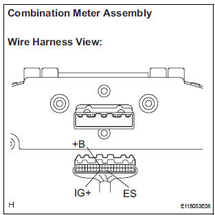
- Check that the connectors are properly connected to the center airbag sensor assembly and the combination meter assembly.
OK: The connectors are properly connected.
 CONNECT CONNECTORS

3 CHECK WIRE HARNESS (SOURCE VOLTAGE OF COMBINATION METER ASSEMBLY)
- Turn the ignition switch to the LOCK position.
- Disconnect the negative (-) terminal cable from the battery, and wait for at least 90 seconds.
- Disconnect the connector from the combination meter assembly.
- Connect the negative (-) terminal cable to the battery, and wait for at least 2 seconds.
- Turn the ignition switch to the ON position.
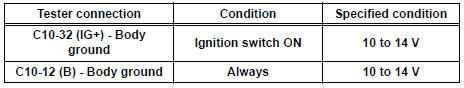
- Measure the voltage according to the value(s) in the table below.
Standard voltage
- Turn the ignition switch to the LOCK position.
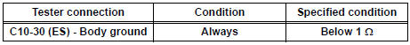
- Measure the resistance according to the value(s) in the table below.
Standard Resistance
 REPAIR OR REPLACE WIRE
HARNESS
REPAIR OR REPLACE WIRE
HARNESS

4 CHECK SRS WARNING LIGHT
- Turn the ignition switch to the LOCK position.
- Disconnect the negative (-) terminal cable from the battery, and wait for at least 90 seconds.
- Connect the connector to the combination meter assembly.
- Disconnect the connector from the center airbag sensor assembly.
- Connect the negative (-) terminal cable to the battery, and wait for at least 2 seconds.
- Turn the ignition switch to the ON position.
- Check the SRS warning light condition.
OK: After the primary check period, SRS warning light goes off for approximately 10 seconds, and remains on. HINT: The primary check period is approximately 6 seconds after the ignition switch is turned to the ON position.
 REPLACE COMBINATION METER
ASSEMBLY
REPLACE COMBINATION METER
ASSEMBLY

REPLACE CENTER AIRBAG SENSOR ASSEMBLY
 SRS Warning Light Remains ON
DESCRIPTION
The SRS warning light is located on the combination meter assembly.
When the SRS is normal, the SRS warning light comes on for approximately 6
seconds after the ignition
switch is t ...
 Diagnosis Circuit
DESCRIPTION
DTC output mode is set by connecting terminals TC and CG of the DLC3.
DTCs are displayed by blinking the SRS warning light.
HINT:
When each warning light stays blinking, a g ...
Other materials:
Compressor and magnetic clutch
COMPONENTS
...
Operation check
NOTICE: Inspection should be started after conforming that
the items listed in the "CUSTOMIZE PARAMETER" for the power back door system
have defaulted to the initial settings
1. CHECK OPENING OPERATION
Conditions necessary for the power back door to
open:
Power back d ...
Inspection
1. INSPECT UNDERDRIVE PLANETARY GEAR PRELOAD
(a) Using SST, fix the underdrive planetary gear
assembly.
SST 09387-00050
(b) Using SST and a torque wrench, measure the
turning torque of the underdrive planetary gear
assembly while rotating the torque wrench at 60
rpm.
SST 09387-00050
...
