Toyota Sienna Service Manual: Diagnosis Circuit
DESCRIPTION
DTC output mode is set by connecting terminals TC and CG of the DLC3.
DTCs are displayed by blinking the SRS warning light.
HINT:
- When each warning light stays blinking, a ground short in the wiring of terminal TC of the DLC3 or an internal ground short in each ECU is suspected.
- A DTC output mode signal is transmitted through BEAN and CAN to each ECU including the center airbag sensor assembly. Thus when all systems do not enter DTC output mode, there may be an ECM malfunction.
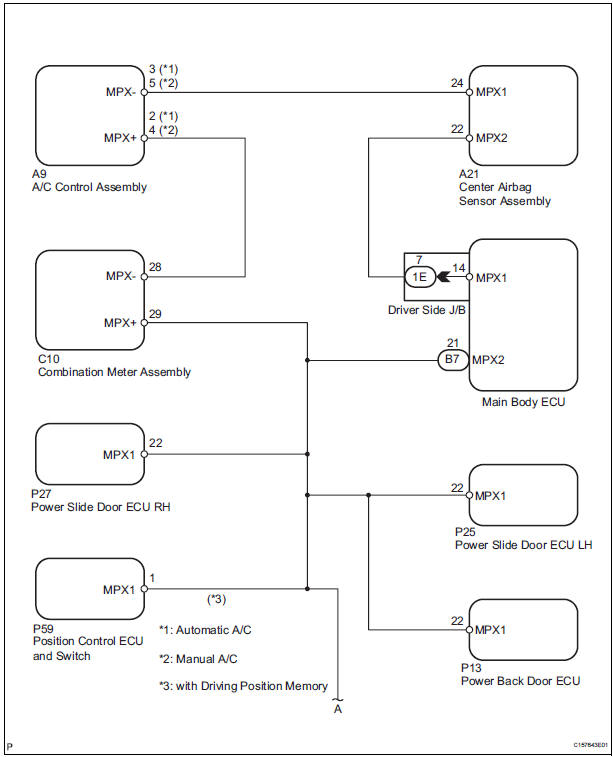
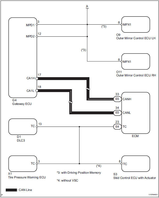
WIRING DIAGRAM
INSPECTION PROCEDURE
1 CHECK MULTIPLEX COMMUNICATION SYSTEM
- Check if the multiplex communication system DTC is output.
HINT: The center airbag sensor assembly of this system is connected to the multiplex communication system.
Therefore, before starting troubleshooting, make sure to check that there is no trouble in the multiplex communication system.
OK: The Multiplex communication system DTC is not output.
2 CHECK CAN COMMUNICATION SYSTEM
- Use the intelligent tester to check if the CAN communication system is functioning normally.
HINT: The ECM is connected to the CAN communication system. Therefore, before starting troubleshooting, make sure to check that there is no trouble in the CAN communication system.
OK: The CAN communication system is functioning normally.
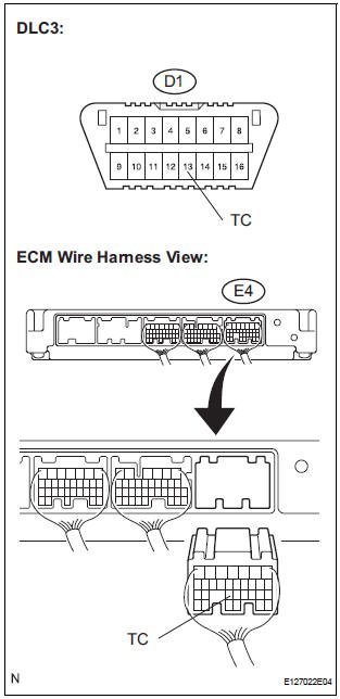
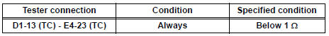
3 CHECK WIRE HARNESS (TC OF DLC3 - TC OF ECM)
- Turn the ignition switch to the LOCK position.
- Disconnect the connector from the ECM.
- Measure the resistance according to the value(s) in the table below.
Standard resistance
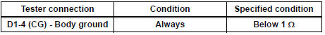
4 CHECK WIRE HARNESS (CG OF DLC3 - BODY GROUND)
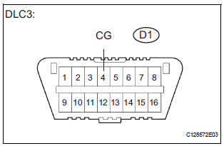
- Measure the resistance according to the value(s) in the table below.
Standard resistance
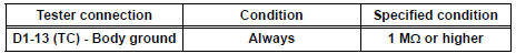
5 CHECK WIRE HARNESS (TC OF DLC3 - BODY GROUND)
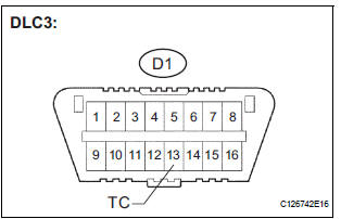
- Measure the resistance according to the value(s) in the table below.
Standard resistance
REPLACE CENTER AIRBAG SENSOR ASSEMBLY
 SRS Warning Light does not Come ON
DESCRIPTION
WIRING DIAGRAM
INSPECTION PROCEDURE
1 CHECK BATTERY
Measure the voltage of the battery.
Standard voltage:
11 to 14 V
2 CHECK CONNECTORS
Turn the ignition switch to the LOCK ...

Other materials:
Bluetooth Module Initialization Failed
DTC 57-47 Bluetooth Module Initialization Failed
DESCRIPTION
DTC No.
DTC Detection Condition
Trouble Area
57-47
Bluetooth module is not installed.
Problem with Bluetooth module
Problem in communication line to Bluetooth module
...
Warning Buzzer Malfunction
DTC P1575 Warning Buzzer Malfunction
DESCRIPTION
The ABS & traction actuator (skid control ECU) receives an alarm demand
signal from the ECM and
operates the skid control buzzer. The buzzer sounds to warn that the distance
between the vehicle in front
and your own vehicle is decreasing.
...
Map Disc Read Error
DTC 58-42 Map Disc Read Error
DTC 80-42 Map Disc Read Error
DESCRIPTION
DTC No.
DTC Detection Condition
Trouble Area
58-42
Player error
Scratches or dirt on the disc
Access to an invalid address due to software error
...
