Toyota Sienna Service Manual: SRS Warning Light does not Come ON
DESCRIPTION
WIRING DIAGRAM
INSPECTION PROCEDURE
1 CHECK BATTERY
- Measure the voltage of the battery.
Standard voltage: 11 to 14 V
2 CHECK CONNECTORS
- Turn the ignition switch to the LOCK position.
- Disconnect the negative (-) terminal cable from the battery, and wait for at least 90 seconds.
- Check that the connectors are properly connected to the center airbag sensor assembly and the combination meter assembly.
OK: The connectors are properly connected.
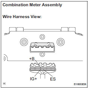
3 CHECK WIRE HARNESS (SOURCE VOLTAGE OF COMBINATION METER ASSEMBLY)
- Turn the ignition switch to the LOCK position.
- Disconnect the negative (-) terminal cable from the battery, and wait for at least 90 seconds.
- Disconnect the connector from the combination meter assembly.
- Connect the negative (-) terminal cable to the battery, and wait for at least 2 seconds.
- Turn the ignition switch to the ON position.
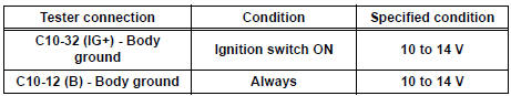
- Measure the voltage according to the value(s) in the table below.
Standard voltage
- Turn the ignition switch to the LOCK position.
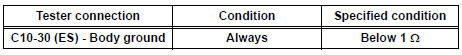
- Measure the resistance according to the value(s) in the table below.
Standard Resistance
4 CHECK SRS WARNING LIGHT
- Turn the ignition switch to the LOCK position.
- Disconnect the negative (-) terminal cable from the battery, and wait for at least 90 seconds.
- Connect the connector to the combination meter assembly.
- Disconnect the connector from the center airbag sensor assembly.
- Connect the negative (-) terminal cable to the battery, and wait for at least 2 seconds.
- Turn the ignition switch to the ON position.
- Check the SRS warning light condition.
OK: After the primary check period, SRS warning light goes off for approximately 10 seconds, and remains on.
HINT: The primary check period is approximately 6 seconds after the ignition switch is turned to the ON position.
REPLACE CENTER AIRBAG SENSOR ASSEMBLY
 SRS Warning Light Remains ON
DESCRIPTION
The SRS warning light is located on the combination meter assembly.
When the SRS is normal, the SRS warning light comes on for approximately 6
seconds after the ignition
switch is t ...
 Diagnosis Circuit
DESCRIPTION
DTC output mode is set by connecting terminals TC and CG of the DLC3.
DTCs are displayed by blinking the SRS warning light.
HINT:
When each warning light stays blinking, a g ...
Other materials:
Fail-safe chart
If any of the following DTCs are set, the ECM enters fail-safe
mode to allow the vehicle to be driven temporarily.
HINT:
*1: The vehicle can be driven slowly when the accelerator
pedal is depressed firmly and slowly. If the accelerator
pedal is depressed quickly, the vehicle may ...
Evaporative Emission System
DTC P043E Evaporative Emission System Reference Orifice
Clog Up
DTC P043F Evaporative Emission System Reference Orifice
High Flow
DTC P2401 Evaporative Emission System Leak Detection
Pump Control Circuit Low
DTC P2402 Evaporative Emission System Leak Detection
Pump Control Circuit High
DTC P ...
Power seat switch
Inspection
1. INSPECT FRONT POWER SEAT SWITCH
Inspect the driver side power seat switch.
Measure the resistance according to the
value(s) in the table below.
Standard resistance:
Slide switch
Front vertical switch
Lifter switch
Reclining switch
If the res ...
