Toyota Sienna Service Manual: Diagnosis system
1. DESCRIPTION
When troubleshooting a vehicle with the diagnosis system, the only difference from the usual troubleshooting procedure is connecting the intelligent tester to the vehicle and reading various data output from the vehicle's clearance warning ECU.
The clearance warning ECU records DTCs when the computer detects a malfunction in the computer itself or in its circuits.
To check the DTCs, connect the intelligent tester to the DLC3 on the vehicle. The intelligent tester enables you to erase the DTCs, activate the various actuators, and check the freeze frame data and Data List.
2. CHECK DLC3
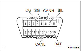
- The ECU uses ISO 15765-4 for communication.
The terminal arrangement of the DLC3 complies with SAE J1962 and matches the ISO 15765-4 format.
If the result is not as specified, the DLC3 may have a malfunction. Repair or replace the harness or connector.
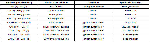
NOTICE: *: Before measuring the resistance, leave the vehicle as is for at least 1 minute and do not operate the ignition switch, any other switches or the doors.
HINT: If the display shows a communication error message after connecting the intelligent tester to the DLC3 and turning the ignition switch to the ON position, there is a problem with either the vehicle or the tool (intelligent tester only).
- If communication is normal when the tester is connected to another vehicle, inspect the DLC3 on the original vehicle.
- If communication is still impossible when the tester is connected to another vehicle, the problem is probably in the tester itself. Consult the Service Department listed in the tester's instruction manual
 Terminals of ECU
1. INSTRUMENT PANEL JUNCTION BLOCK
(MULTIPLEX NETWORK BODY ECU)
Disconnect the B6, B7 and B9 ECU connectors.
Disconnect the 1A, 1C, 1K, 1L and 1P J/B
connectors.
Check the vol ...
 DTC check / clear
1. DTC CHECK/CLEAR (USING INTELLIGENT TESTER:)
DTC check
Connect the intelligent tester to the DLC3.
Turn the ignition switch to the ON position.
Read the DTCs on t ...
Other materials:
System description
1. DESCRIPTION OF OCCUPANT CLASSIFICATION SYSTEM
GENERAL DESCRIPTION.
In the occupant classification system, the
occupant classification ECU calculates the
weight of the occupant based on a signal from
the occupant classification sensors. This system
recognizes the occu ...
Short to B+ in Front Passenger Side Squib Circuit
DTC B0108/52 Short to B+ in Front Passenger Side Squib Circuit
DESCRIPTION
The front passenger side squib circuit consists of the center airbag sensor
assembly and the front
passenger airbag assembly.
The circuit instructs the SRS to deploy when deployment conditions are met.
DTC B0108/52 ...
USE SIMULATION METHOD TO CHECK
DTC B0113/42 Short to B+ in Side Squib RH Circuit
DESCRIPTION
The side squib RH circuit consists of the center airbag sensor assembly and
the front seat side airbag
assembly RH.
This circuit instructs the SRS to deploy when deployment conditions are met.
DTC B0113/42 is recorded when a sh ...
