Toyota Sienna Service Manual: Disassembly
1. REMOVE INDICATOR LIGHT WIRE SUB-ASSEMBLY
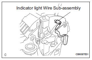
(a) Remove the indicator light wire sub assembly from the position indicator light guide.
2. REMOVE POSITION INDICATOR LIGHT BULB
(a) Remove the shift position indicator light bulb from the indicator light wire sub-assembly
3. REMOVE POSITION INDICATOR SLIDE COVER
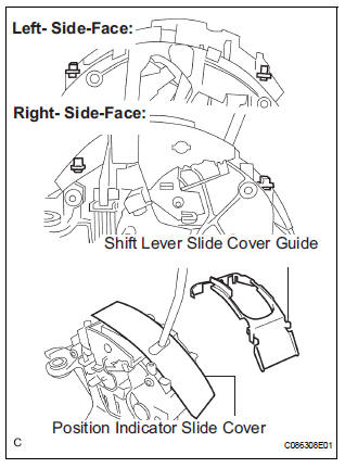
(a) Remove the shift lever slide cover guide from the shift lever assembly.
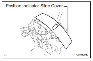
(b) Remove the position indicator slide cover from the shift lever assembly.
4. REMOVE POSITION INDICATOR SLIDE COVER
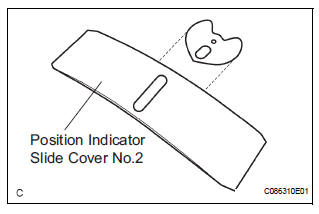
(a) Remove the position indicator slide cover No.2 from the position indicator slide cover.
 Removal
1. DISCONNECT BATTERY NEGATIVE TERMINAL
2. REMOVE FRONT DOOR SCUFF PLATE LH
HINT:
(See page IP-6)
3. REMOVE FRONT DOOR SCUFF PLATE RH
HINT:
(See page IP-6)
4. REMOVE COWL SIDE TRIM BOARD LH
HI ...
 Adjustment
1. INSPECT SHIFT LEVER POSITION
(a) When shifting from P to R position only with ignition
switch ON and brake pedal, make sure that the
shifting lever moves smoothly and can be
moderately operated ...
Other materials:
Reassembly
1. INSTALL LH REAR BUMPER SIDE RETAINER
Install the LH rear bumper side retainer with the 3
screws.
2. INSTALL RH REAR BUMPER SIDE RETAINER
Install the RH rear bumper side retainer with the 3
screws.
3. INSTALL REAR BUMPER REINFORCEMENT SUBASSEMBLY
Install the rear bumper reinf ...
Short to B+ in Curtain Shield Squib LH Circuit
DTC B1168/86 Short to B+ in Curtain Shield Squib LH Circuit
DESCRIPTION
The curtain shield squib LH circuit consists of the center airbag sensor
assembly and the curtain shield
airbag assembly LH.
The circuit instructs the SRS to deploy when deployment conditions are met.
DTC B1168/86 is ...
Throttle / Pedal Position Sensor/ Switch
DTC P2120 Throttle / Pedal Position Sensor / Switch "D"
Circuit
DTC P2122 Throttle / Pedal Position Sensor / Switch "D"
Circuit Low Input
DTC P2123 Throttle / Pedal Position Sensor / Switch "D"
Circuit High Input
DTC P2125 Throttle / Pedal Position Sensor / Switch ...
