Toyota Sienna Service Manual: Terminals of ECU
1. INSTRUMENT PANEL JUNCTION BLOCK (MULTIPLEX NETWORK BODY ECU)
- Disconnect the B6, B7 and B9 ECU connectors.
- Disconnect the 1A, 1C, 1K, 1L and 1P J/B connectors.
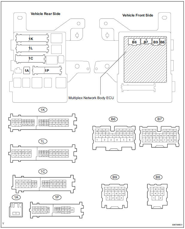
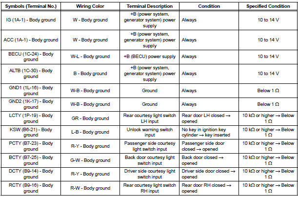
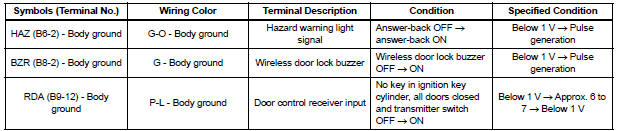
- Check the voltage or resistance according to the value(s) in the table below (wire harness side connector).
HINT: If the result is not as specified, there may be a malfunction on the wire harness side.
- Reconnect the B6, B7 and B9 ECU connectors.
- Reconnect the 1A, 1C, 1K, 1L and 1P J/B connectors.
- Check the voltage according to the value(s) in the table below (ECU side connector).
If the result is not as specified, the instrument panel J/B (multiplex network body ECU) may have a malfunction.
 Problem symptoms table
HINT:
Inspect the fuse and relay before investigating the suspected
areas shown in the table below.
WIRELESS DOOR LOCK CONTROL SYSTEM:
...
 Diagnosis system
1. DESCRIPTION
When troubleshooting a vehicle with the diagnosis
system, the only difference from the usual
troubleshooting procedure is connecting the intelligent
tester to the vehicle and readin ...
Other materials:
Heater relay (for rear air conditioning system)
ON-VEHICLE INSPECTION
1. INSPECT REAR HEATER RELAY
(a) Remove the rear heater relay.
(b) Measure the resistance according to the value(s) in
the table below.
Standard resistance
If the resistance is not as specified, replace the rear
heater relay. ...
PCS (Pre-Collision
System)
When the radar sensor detects possibility of a frontal collision,
the pre-collision system such as the brakes and seat belts are
automatically engaged to lessen impact as well as vehicle damage.
Pre-collision warning
When a high possibility of a
frontal collision is detected, the
pre-colli ...
Message Settings
Display the “Phone/Message Settings” screen.
Select “Messaging Settings”.
Select the desired item to be set.
Set automatic message
transfer on/off.
Set automatic message
readout on/off.
Set the SMS/MMS notification
popup on/off.
Set the e-mail notification
pop ...
