
Toyota Sienna Service Manual: Diagnosis system
1. CHECK DLC3
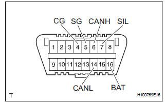
- The ECU uses the ISO 15765-4 for communication protocol. The terminal arrangement of the DLC3 complies with SAE J1962 and matches the ISO 15765-4 format.
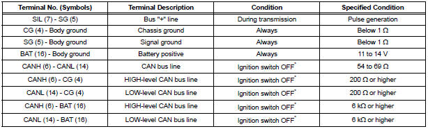
NOTICE: *: Before measuring the resistance, leave the vehicle as is for at least 1 minute and do not operate the ignition switch, any other switches, or the doors.
If the result is not as specified, the DLC3 may have a malfunction. Repair or replace the harness and connector.
HINT: If the display shows an error message after having connected the cable of the intelligent tester to the DLC3, turned the ignition switch to the ON position, and operated the tester, there is a problem on either the vehicle side or the tool side.
- If communication is normal when the tester is connected to another vehicle, inspect the DLC3 of the original vehicle.
- If communication is still not possible when the tester is connected to another vehicle, the problem may be in the tester itself. Consult the Service Department listed in the tester's instruction manual.
 Terminals of ECU
1. COMBINATION METER ASSEMBLY
*1: with Power Rear No. 2 Seat with Stowing Function
*2: with Theft Deterrent System
Waveform 1 (Reference) : Using an oscilloscope:
OK ...
 Data list / active test
1. DATA LIST
Using the intelligent tester to read the Data List allows
the values or states of switches, sensors, actuators and
other items to be read without removing any parts. This
non-intrusiv ...
Other materials:
Wireless remote control
Vehicles without a smart key system (type A)
Locks all doors
Unlocks all doors
Sounds the alarm
Vehicles without a smart key system (type B)
Locks all doors
Unlocks all doors
Opens and closes the left side power sliding door
Opens and closes the right sid ...
Transmitter battery
REPLACEMENT
1. REMOVE TRANSMITTER BATTERY
NOTICE:
Special caution should be taken for handling each
component as they are precision electronic
components.
Using a coin or the equivalent, pry out the
transmitter case.
NOTICE:
Do not forcibly pry out the case.
Re ...
If your vehicle overheats
The following may indicate that your vehicle is overheating.
The needle of the engine coolant temperature gauge
enters the red zone or a loss of engine power is experienced. (For
example, the vehicle speed does not increase.)
The warning message indicating overheats is shown on the
mult ...
